Fuel tank protector shield

a technology for protecting shields and fuel tanks, applied in vehicle arrangements, roofs, transportation and packaging, etc., can solve the problems of damage to the fuel sending unit, damage to the mason ring or the sending unit of the fuel tank, and the damage to the mason ring or the sending unit, so as to reduce the impact force and reduce the impact force to a body. , the effect of lessening the impact for

Inactive Publication Date: 2006-05-18
FORD GLOBAL TECH LLC
View PDF21 Cites 6 Cited by
  • Summary
  • Abstract
  • Description
  • Claims
  • Application Information

AI Technical Summary

Benefits of technology

[0008] A shield for an automotive vehicle is provided to lessen the impact force to a foreign body by absorbing energy or converting energy from the foreign body when it contacts the shield. The shield reduces the impact force to a body by using crushable ribs or ridges to absorb some of the impact energy. The shield reduces the impact force to a body by using a ramped surface to divert the otherwise direct contact between two members into sliding motion along the ramped surface of the shield.
[0009] Briefly, the shield has a ramped surface, an inner surface, and a periphery delineating the inner surface from the ramped surface. The inner surface is further refined into an upper area and a lower area, where a ridge extends from the inner surface portioning the upper area from the lower area. At least one rib is connected to the ridge and extends from the inner surface, whereby the ridge or the rib may absorb energy or divert direct contact into sliding contact when the ramped surface is impacted by a foreign body reducing the impact force upon the foreign body.
[0010] Also, a method of using a shield in an automotive vehicle is provided. The method of using a shield in accordance with the present invention upon an automotive vehicle includes: positioning the shield upon a cross member and locating the shield in the dislodgment path between the cross member and a mason ring of a tank; and, attaching the shield to the cross member. Additionally, a method of using a shield may include identifying the dislodgment path and placing the ramped surface of the shield in the dislodgment path. Moreover, an attack angle may be identified allowing for sufficient slope for increase energy diversion by changing direct contact into sliding contact. Furthermore, by selecting the appropriate materials an otherwise metal-to-metal contact may be changed into a plastic-to-metal contact reducing undesirable affects.

Problems solved by technology

In one such development barrier crash test, it was noted that damage to a fuel-sending unit on a 29-gallon fuel tank was observed.
The impact of the mason ring with the cross member had the undesirable affect of causing damage to the mason ring.
However, the mason ring or sending unit of the fuel tank is not protected.
However, it fails to disclose a shield that can reduce the impact force caused by the impingement of the filler cap into a cross member.
However, it also fails to disclose a shield that can reduce the impact force caused by the tank armature into a cross member.

Method used


Image

  • Fuel tank protector shield
  • Fuel tank protector shield
  • Fuel tank protector shield

Examples


first embodiment

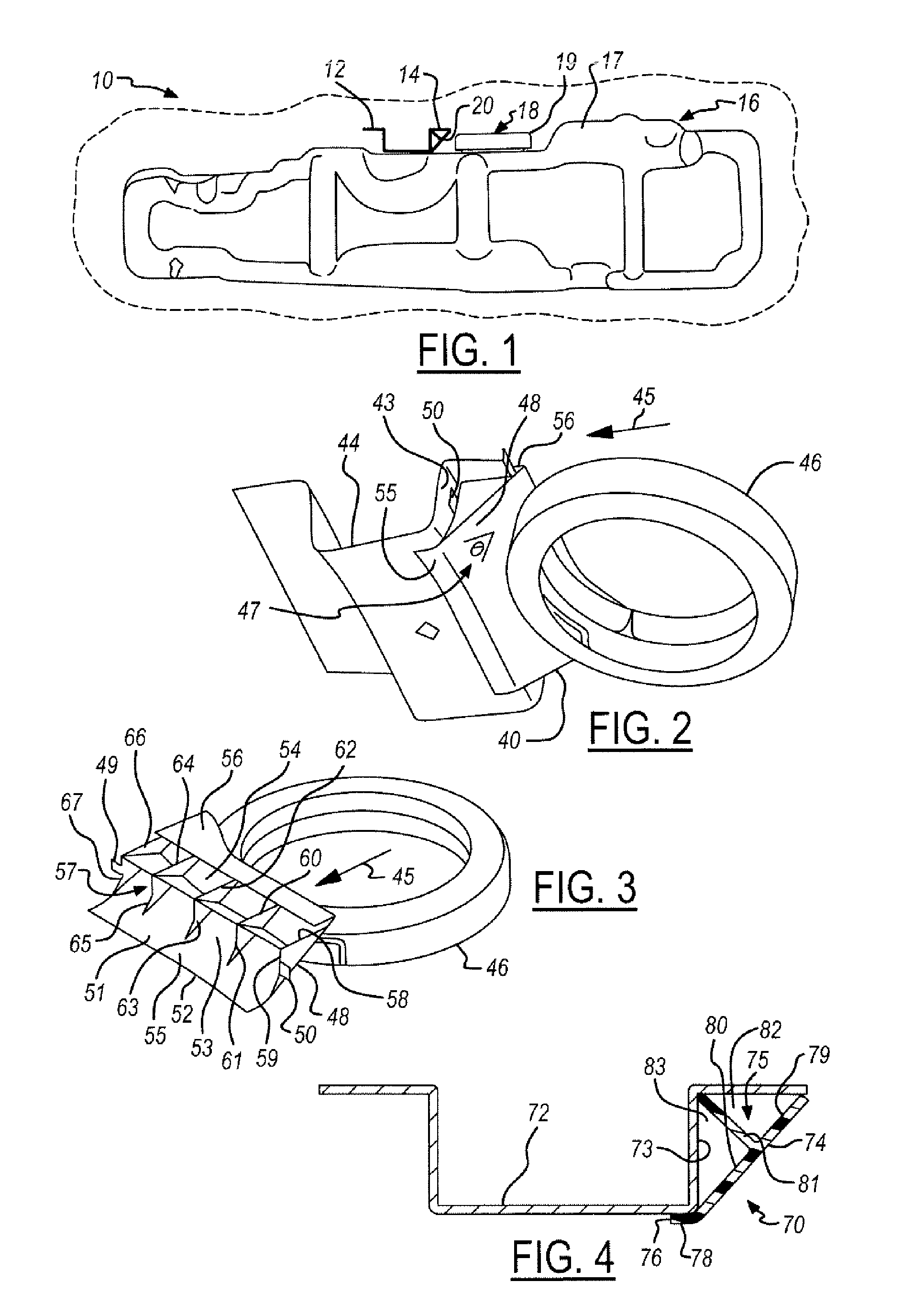
[0020]FIG. 1 illustrates a cutaway side view the shield 20 used in an automotive vehicle 10 to advantage. The automotive vehicle 10 includes a cross member 12, a fluid reservoir tank 16 and a shield 20. The inventive shield 20 reduces the impact force to the fluid reservoir tank 16 should the fluid reservoir tank 16 be accelerated toward the cross member 12 or the cross member12 be accelerated toward the fluid reservoir tank 16.

[0021] The cross member 12 has a first side 14 in which the shield 20 may be attached or connected. A person of skill in the art will recognize that the shield 20 may be attached or connected to any of the other sides of the cross member 12, but will be used to advantage if positioned as suggested below.

[0022] The fluid reservoir tank 16 has a container 17, a lid 18, and a mason ring 19. The lid 18 is securely sealed to the container 17 by mason ring 19. A person of skill in the art will recognize that the lid 18 and mason ring 19 may be formed from a single...

second embodiment

[0048]FIG. 4 is a cross-sectional view of the shield 70 being used to advantage. The vehicle (not shown) includes a cross member 72, a reservoir 71 and a shield 70. The inventive shield 70 reduces the impact force to the reservoir 71 should the reservoir 71 be accelerated toward the cross member 72 in the direction of the shield 70.

[0049] The cross member 72 has a first side 73 in which the shield 70 may be attached or connected to the cross member 72. A person of skill in the art will recognize that the shield 70 may be attached or connected to any of the other sides of the cross member 72, but will be used to advantage if positioned within the directional path as described above.

[0050] In the present embodiment, the shield 70 is attached to the first side 73 of the cross member 72 and positioned between the reservoir 71 and the cross member 72 in the normal direction of vehicle travel. The shield 70 may be used to advantage by absorbing energy should the reservoir 71 impact the s...

third embodiment

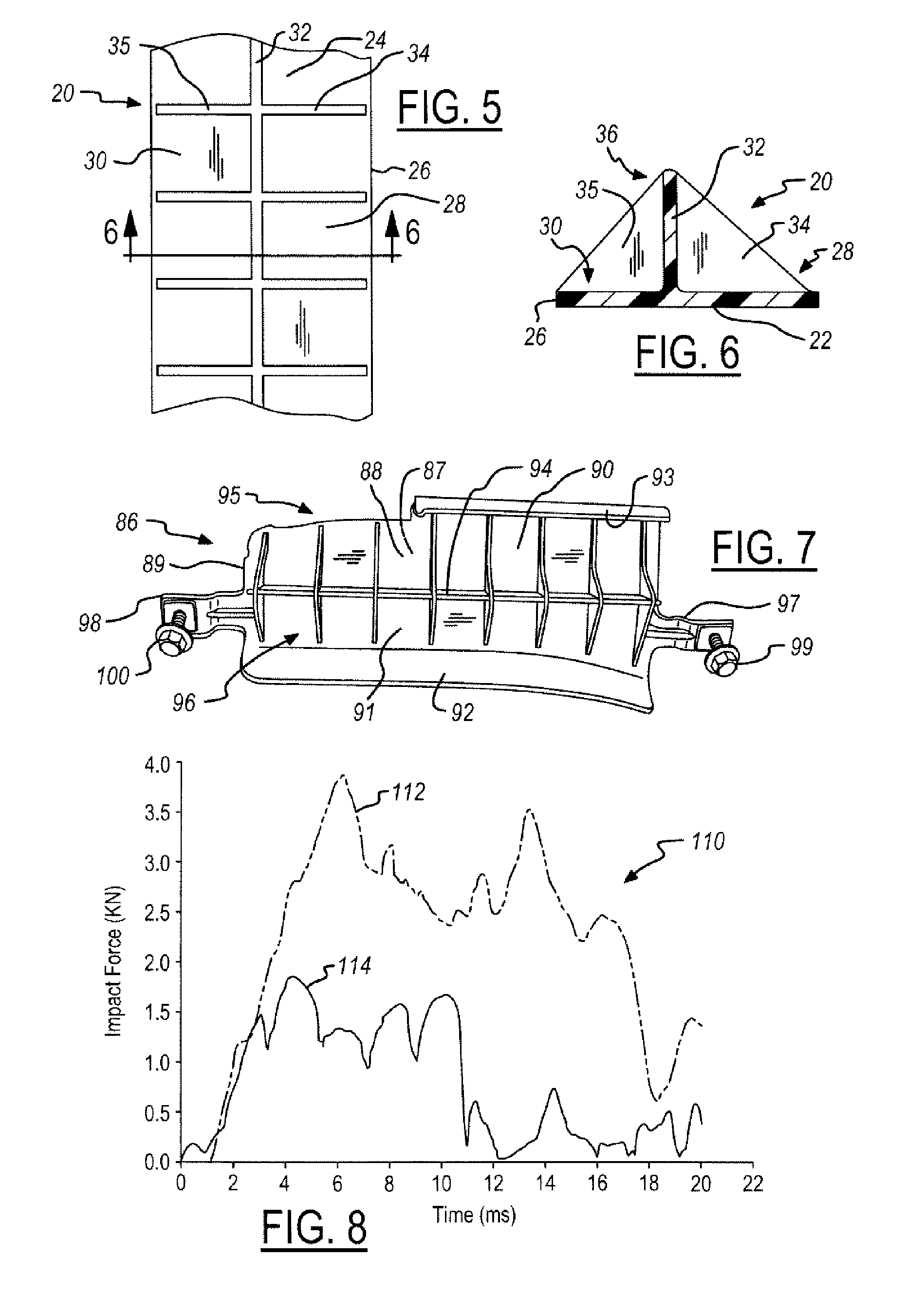
[0057]FIG. 7 is a perspective view of the shield 86. The present embodiment of the shield 86 has similarities to the two-dimensional representation of the shield 40 as shown in FIGS. 2 and 3. Moreover, this shield 86 is designed to fit upon a non-uniform cross member of a vehicle.

[0058] In the present embodiment, he shield 86 includes a ramped surface 87, an inner surface 88 and a periphery 89. The periphery 89 delineates the inner surface 88 from the ramped surface 87. As represented in the present embodiment, the ramped surface 87, the inner surface 88 and the periphery 89 form a solid body.

[0059] The inner surface 88 of the shield 86 is further divided into an upper area 90 and a lower area 91. The shield 86 includes a ridge 94 that extends perpendicularly from the inner surface. In the present embodiment, the ridge 94 approximately proportions the upper area 90 from the lower area 91. The ridge 94 extends from the periphery 89 on one end of the shield 86 to the periphery 89 on ...


PUM


Abstract

A shield (20) for an automotive vehicle (10) is provided to lessen the impact force to a foreign body by absorbing energy or converting energy from the foreign body with the shield (20). The shield (20) has a ramped surface (22), an inner surface (24), and a periphery (26) delineating the inner surface (24) from the ramped surface (22). The inner surface (24) is further refined into an upper area (28) and a lower area (30), where a ridge (32) extends from the inner surface (24) portioning the upper area (28) from the lower area (30). At least one rib (34) is connected to the ridge (32) and extends from the inner surface (24), whereby the ridge (32) or the rib (34) may absorb energy or divert direct contact into sliding contact when the ramped surface (22) is impacted by a foreign body reducing the impact force upon the foreign body. Also, a method of using a shield (20) in an automotive vehicle 10 is provided.

Description

TECHNICAL FIELD [0001] The present invention generally relates to protector shields for automotive vehicles and, more particularly, to fuel tank protector shield for automotive vehicles. BACKGROUND OF THE INVENTION [0002] The automotive industry, in order to improve vehicle safety, has developed barrier crash testing as a method by which unanticipated failures to vehicles may be detected. By observing the unanticipated failures, appropriate countermeasure may be taken to improve the robustness of the vehicle thereby eliminating the failure altogether or providing insight to the engineering and design of alternative solutions. [0003] In one such development barrier crash test, it was noted that damage to a fuel-sending unit on a 29-gallon fuel tank was observed. Upon further investigation, it was noted that the mason ring that secures the fuel-sending unit to the fuel tank had impacted a structural cross member during the crash test. The impact of the mason ring with the cross member...

Claims


Application Information

Patent Timeline
Patent Type & Authority Applications(United States)
IPC IPC(8): B62D25/20
CPCB62D21/152B62D25/2027B62D29/041
Inventor PELLILLO, ROBERTWANG, WEIMAHADEVAN, KUMARDOONG, JIAMAW
Owner FORD GLOBAL TECH LLC
Why Eureka
Try Eureka