System and method for testing dynamic resistance during thermal shock cycling

a dynamic resistance and thermal shock technology, applied in the field of thermal shock testing, can solve the problems of large amount of time and money, deception of measurements, and difficulty in observing the onset of failures (e.g., cracks), and achieve the effect of facilitating a fast, accurate, real-time continuous tes

Inactive Publication Date: 2006-05-18
MOTOROLA INC
View PDF11 Cites 11 Cited by
  • Summary
  • Abstract
  • Description
  • Claims
  • Application Information

AI Technical Summary

Benefits of technology

[0013] Briefly, in accordance with the present invention, disclosed is an innovative test method and system that addresses the shortcomings of the conventional test methods. Unlike traditional failure detection methods, when used with thermal environmental chambers, the present

Problems solved by technology

For this reason, manufacturers spend vast amounts of time and money finding and eliminating failures from products before beginning the mass-production stage.
Because the rate and maximum variation of material expansion or contraction is not uniform in all materials, the changes in temperature can cause a first material to expand and separate from a second material that has a lower expansion delta or slower expansion rate.
A disadvantage of thermal shock tests is that the DUT is contained within the chamber which contains temperatures unsafe for human presence, making it difficult to observe the onset of failures (e.g., cracks) and detect location of failures during any cycle of the test.
The DUT can be tested thoroughly after the temperature cycling is completed, however, the measurements can be deceiving.
At a

Method used


Image

  • System and method for testing dynamic resistance during thermal shock cycling
  • System and method for testing dynamic resistance during thermal shock cycling
  • System and method for testing dynamic resistance during thermal shock cycling

Examples


Embodiment Construction

[0024] As required, detailed embodiments of the present invention are disclosed herein; however, it is to be understood that the disclosed embodiments are merely exemplary of the invention, which can be embodied in various forms. Therefore, specific structural and functional details disclosed herein are not to be interpreted as limiting, but merely as a basis for the claims and as a representative basis for teaching one skilled in the art to variously employ the present invention in virtually any appropriately detailed structure. Further, the terms and phrases used herein are not intended to be limiting; but rather, to provide an understandable description of the invention.

[0025] The terms “a” or “an”, as used herein, are defined as one or more than one. The term plurality, as used herein, is defined as two or more than two. The term another, as used herein, is defined as at least a second or more. The terms including and / or having, as used herein, are defined as comprising (i.e., ...


PUM


Abstract

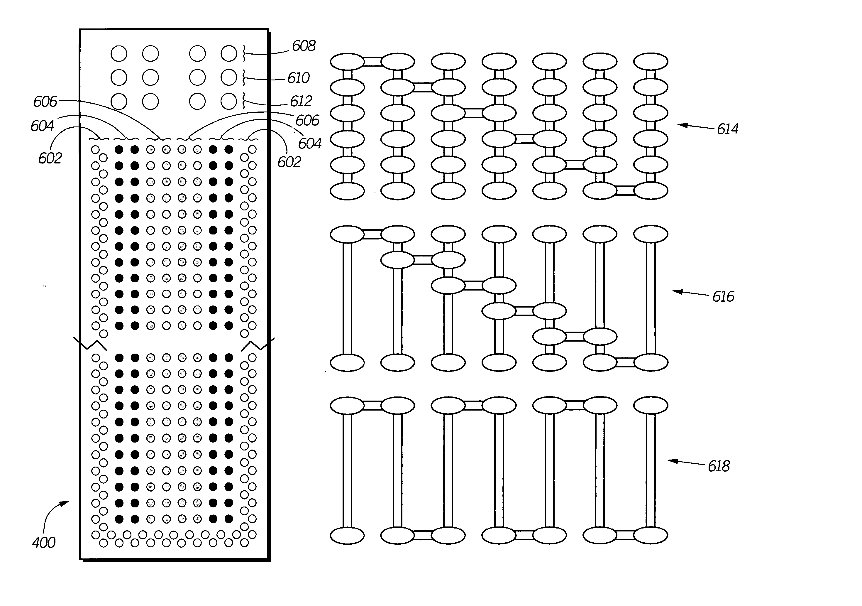
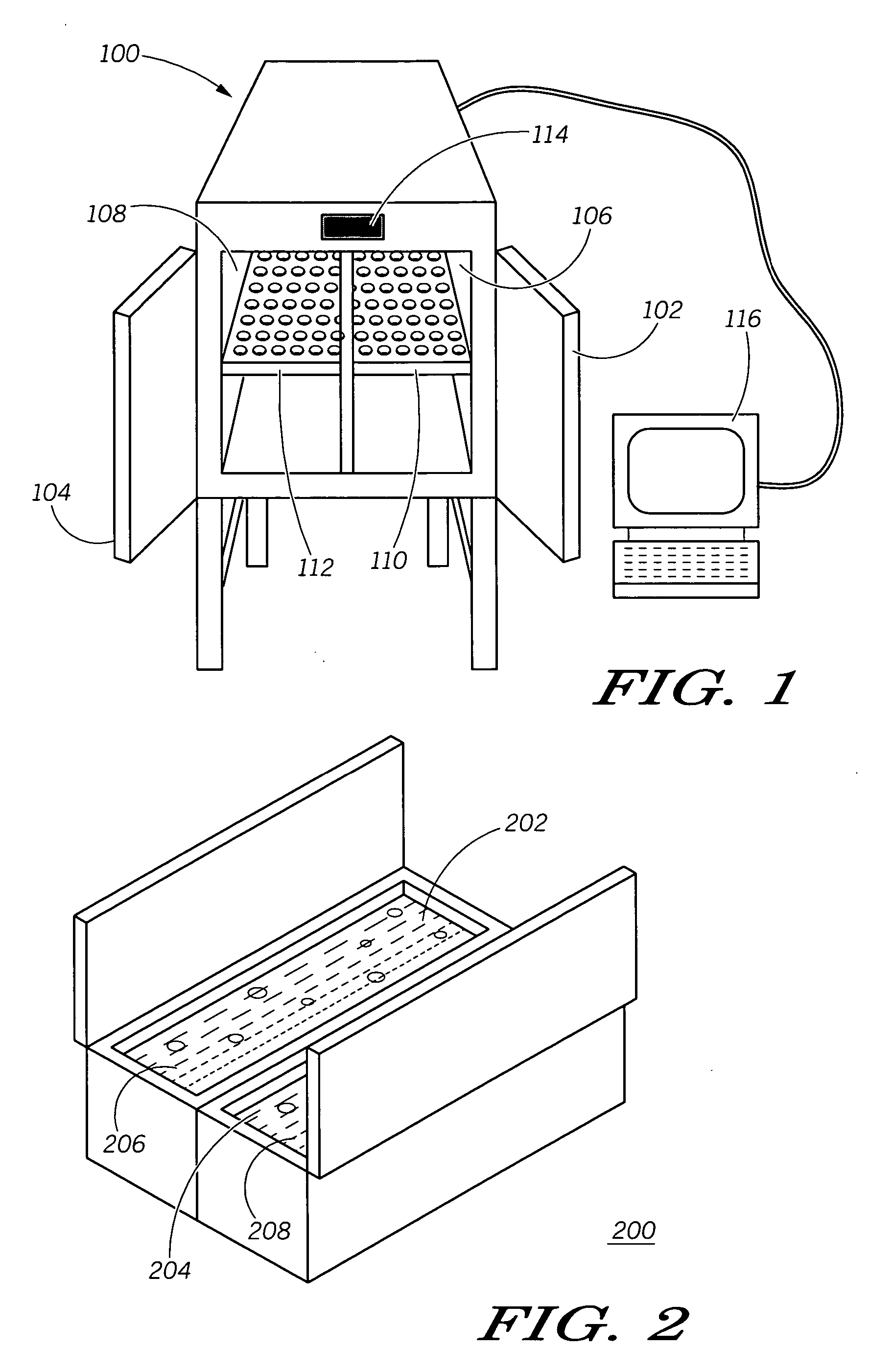
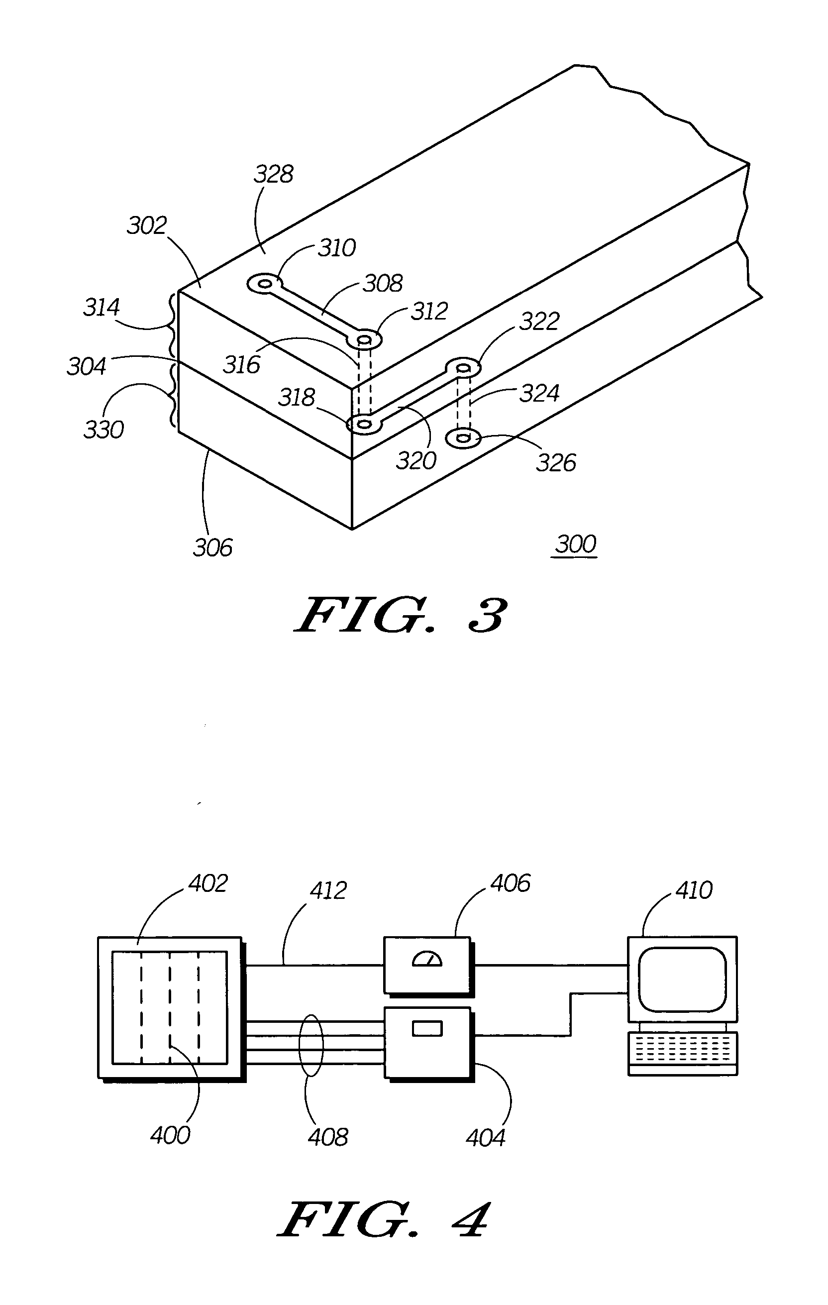
A system includes a temperature chamber (100), a text fixture (402), a test coupon (400), a data acquisition unit (404), an ohmmeter (406) and a computer (410). The temperature chamber (100) provides temperature extremes to the test coupon (400). The test coupon (400) includes a substrate (314), one or more vias (418-429) and traces (402-412) connecting the vias. The data acquisition unit (404) continuously measures a resistance value of the circuit formed by the vias (418-429) and traces (402-412) during temperature cycling of the test coupon (400) held by the test fixture (402). The ohmmeter (406) measures the temperature of the test coupon (400) with a thermocouple. The data is used to detect failures of the materials in the test coupon (400) during the temperature cycling.

Description

FIELD OF THE INVENTION [0001] The present invention generally relates to the field of thermal shock testing, and more particularly relates to continuous fault detection during thermal shock cycling. BACKGROUND OF THE INVENTION [0002] The benchmark of product quality is reliability. Manufacturers of the most reliable products in a particular field are usually the most likely to succeed in the marketplace. For this reason, manufacturers spend vast amounts of time and money finding and eliminating failures from products before beginning the mass-production stage. This process of eliminating failures involves careful design and testing of each component in a product, with the type of test performed varying with the particular component and the intended use of the product. [0003] For electronic circuit boards with plated-through holes, microvias, solder joints, battery contacts, embedded passive components, micro-ball-grid arrays, and other similar structures, a long-accepted method of r...

Claims


Application Information

Patent Timeline
IPC IPC(8): G01R31/02
CPCG01R31/287G01R31/2874G01R31/2879G01R31/2884H05K1/0268H05K3/0011H05K2203/162
Inventor DESAI, NITIN B.CRANDALL, PAUL R.LISAK, ILYAMULLIGAN, ROBERT J.TRACY, JAMES L.ZOLLO, JAMES A.
Owner MOTOROLA INC
Why Eureka
Try Eureka