
Focus test mask, focus measurement method and exposure apparatus

Active Publication Date: 2006-05-18
NIKON CORP
View PDF5 Cites 19 Cited by
  • Summary
  • Abstract
  • Description
  • Claims
  • Application Information

AI Technical Summary

Benefits of technology

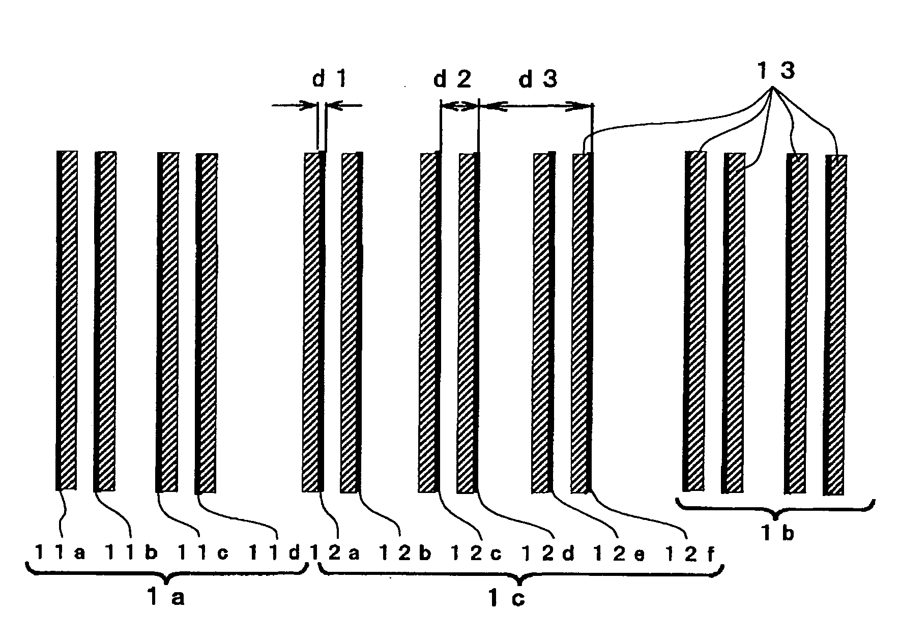
[0016] According to the present invention, it is possible to form a plurality of line patterns as respective isolated lines, and, by detecting the positions of the images of the plurality of line patterns, it is possible to measure any shift between these positions and the position of an image of a reference pattern with a high degree of accuracy.
[0039] According to the present invention, it is possible to provide a focus test mask that enables a pattern to be exposed under the same conditions as the actual exposure conditions and that has a test pattern that can be measured by an alignment microscope that is provided inside the exposure apparatus, and to provide a measurement method and an exposure apparatus that use this focus test mask.

Problems solved by technology

However, in the measuring of this box pattern, there are only two patterns being measured in each of two orthogonal directions, and it is recognized that when the measurement is made using image pickup elements of an alignment system arranged inside the exposure apparatus then there is a low level of measurement accuracy.
Because of this, this measurement method has the drawback that if there is a large amount of defocus and the position movement exceeds half the pitch between diffraction gratings, then measurement is not possible.
However, in these asymmetrical diffraction grating patterns, because one of either positive primary diffracted light and negative primary diffracted light is set to substantially zero, there is a possibility that the exposure amount will be insufficient when the pattern is exposed on a substrate.

Method used


Image

  • Focus test mask, focus measurement method and exposure apparatus
  • Focus test mask, focus measurement method and exposure apparatus
  • Focus test mask, focus measurement method and exposure apparatus

Examples


Embodiment Construction

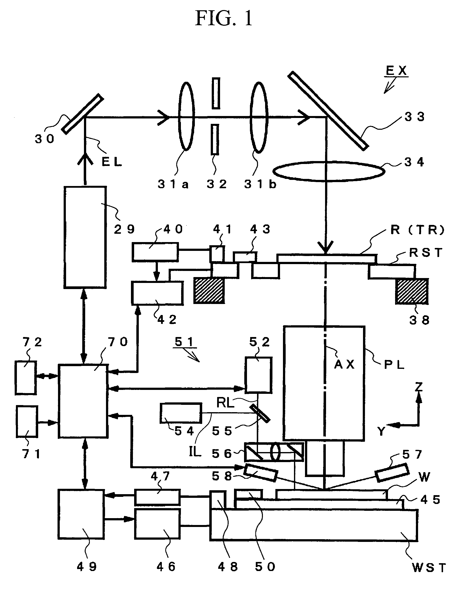
[0048] An embodiment obtained by embodying the present invention in a scan exposure type of exposure apparatus that is used in the manufacture of semiconductor devices will now be described based on FIGS. 1 through 6.

[0049] As is shown in FIG. 1, an exposure apparatus EX of the present embodiment transfers by projection a circuit pattern that is formed on a reticule R serving as a mask onto a wafer W serving as a substrate. Exposure light EL that is irradiated from an illumination optical system 29 that includes an exposure light source, a collimator lens, an interference filter, a fly-eye lens, an aperture diaphragm (i.e., a σ diaphragm) and the like is reflected by a beam splitter 30. The exposure light EL may be, for example, excimer laser light such as KrF, ArF, or F2, higher harmonics such as a metal vapor laser or a YAG laser, or bright lines from an extra-high pressure mercury lamp such as g-lines, h-lines, and i-lines. The exposure light EL that is reflected by the beam spl...


PUM


Abstract

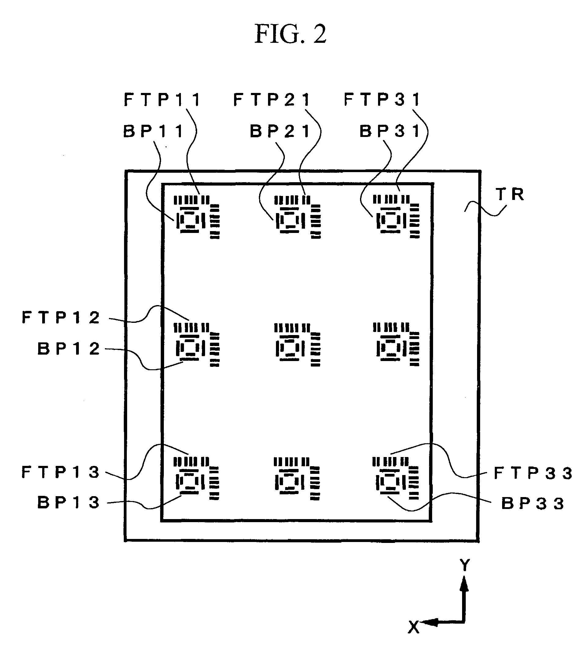
This focus test mask is provided with a test pattern that is projected onto a wafer via a projection optical system. This test pattern includes: a plurality of line patterns that are lined up in a direction of measurement; phase shift sections that are provided in areas adjacent to each of the plurality of line patterns and that are used to shift the phase of light passing through; and reference patterns that are used to obtain an image that forms a reference when the shift in the line pattern image is measured. Spaces between the plurality of line patterns are set at a size that allows each line pattern to be regarded as equivalent to being isolated lines.

Description

CROSS-REFERENCE TO RELATED APPLICATION [0001] This is a Continuation Application of International Application No. PCT / JP2004 / 009683, filed Jul. 1, 2004, which claims priority to Japanese Patent Application No. 2003-190791, filed Jul. 3, 2003. The contents of the aforementioned applications are incorporated herein by reference.BACKGROUND OF THE INVENTION [0002] 1. Field of the Invention [0003] The present invention relates to an exposure mask that is used in the field of semiconductors, a focus measurement method, and an exposure apparatus. [0004] 2. Description of Related Art [0005] Conventionally, a test pattern that is provided on a test reticule is formed on a substrate via a projection optical system, and the optical characteristics of this projection optical system are measured by measuring these formed marks. In recent years, a greater degree of focusing accuracy has been demanded, and a more accurate measurement method is also demanded for the focus positions of projection op...

Claims


Application Information

Patent Timeline
IPC IPC(8): G03B27/52G03F1/00G03F7/20G03F7/207
CPCG03F1/14G03F1/26G03F7/70641G03F1/44G03F1/62G03F1/38
Inventor KONDO, SHINJIRO
Owner NIKON CORP
Learn More