
Low-complexity deblocking filter

a filter and low-complexity technology, applied in the field of video coding, can solve the problems of affecting the quality of the overall video image, and the reference frame used for generating predictions for the coding of subsequent frames will contain blocking artifacts, so as to minimise coding artifacts, minimise coding artifacts, and minimise coding artifacts

Active Publication Date: 2006-05-18
CISCO SYST CANADA
View PDF9 Cites 77 Cited by
  • Summary
  • Abstract
  • Description
  • Claims
  • Application Information

AI Technical Summary

Benefits of technology

[0042] In a still further aspect of the invention there is provided a method of filtering samples to minimise coding artifacts introduced at a block boundary in a block-based video encoder, the method having the steps of checking content activity on every line of samples belonging to the boundary to be filtered and determining whether the filtering process will modify the sample values on said line of samples based on content activity thresholds that are dependent on a quantization parameter and determined using a filter offset parameter.
[0044] In a still further aspect of the present invention there is provided a method of filtering samples to minimise coding artifacts introduced at a block boundary in a block-based video encoder for a line of samples to be filtered across a block boundary that is also a macroblock boundary, where at least one side of the boundary is intra coded, the method having the step of: selecting a strong filtering sub-mode for either side of said block boundary between at least two strong filtering sub-modes, a 3-tap filter sub-mode and an alternative 5-tap filter sub-mode, with the selection between these two sub-modes based on the sample values on each line of samples across the boundary.

Problems solved by technology

Since the coding is block-based, the errors that are introduced by the quantization process tend to produce artifacts in the form of sharp transitions in image intensity across transform block boundaries in the reconstructed frame.
The appearance of blocking significantly affects the natural smoothness seen in video images and leads to a degradation of the overall video image quality.
Blocking artifacts are inherent in hybrid block-based video coders, especially in low bit rate video applications.
However, this scheme has a disadvantage in that the reference frames that are used for generating predictions for the coding of subsequent frames will contain blocking artifacts.
This can lead to reduced coding efficiency and degraded visual quality.
Among the disadvantages of the above described known method is that it permits switching between two filtering modes with very different characteristics at the level of each line of samples within a boundary segment.
This switching adds complexity to the filtering process and can significantly increase the worst-case critical path for processing on many architectures.
Further disadvantages include the particular values in the tables of filtering parameters, ALPHA (α) and BETA (β), which are not optimized to produce the best subjective viewing quality of reconstructed and filtered video.
This hinders optimization of the subjective quality of the decoded video for different types of video content and displays.
This recursive filtering method presents a disadvantage as the values of P0 and Q0 must be computed before the computation of P0 and Q1 can begin.
This design can impede parallel processing of the different samples and thereby increases the critical path for the default mode filtering on most hardware architectures.
An additional disadvantage in the default mode filtering process of the known method is that the calculation of the clipping parameter, C, for chroma samples is unnecessarily complex.
Filtering with this set of equations can lead to insufficient reduction in the visibility of blocking artifacts.

Method used


Image

  • Low-complexity deblocking filter
  • Low-complexity deblocking filter
  • Low-complexity deblocking filter

Examples


Embodiment Construction

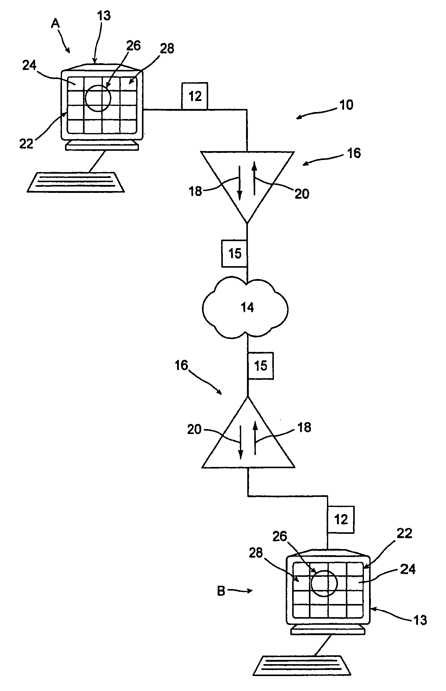
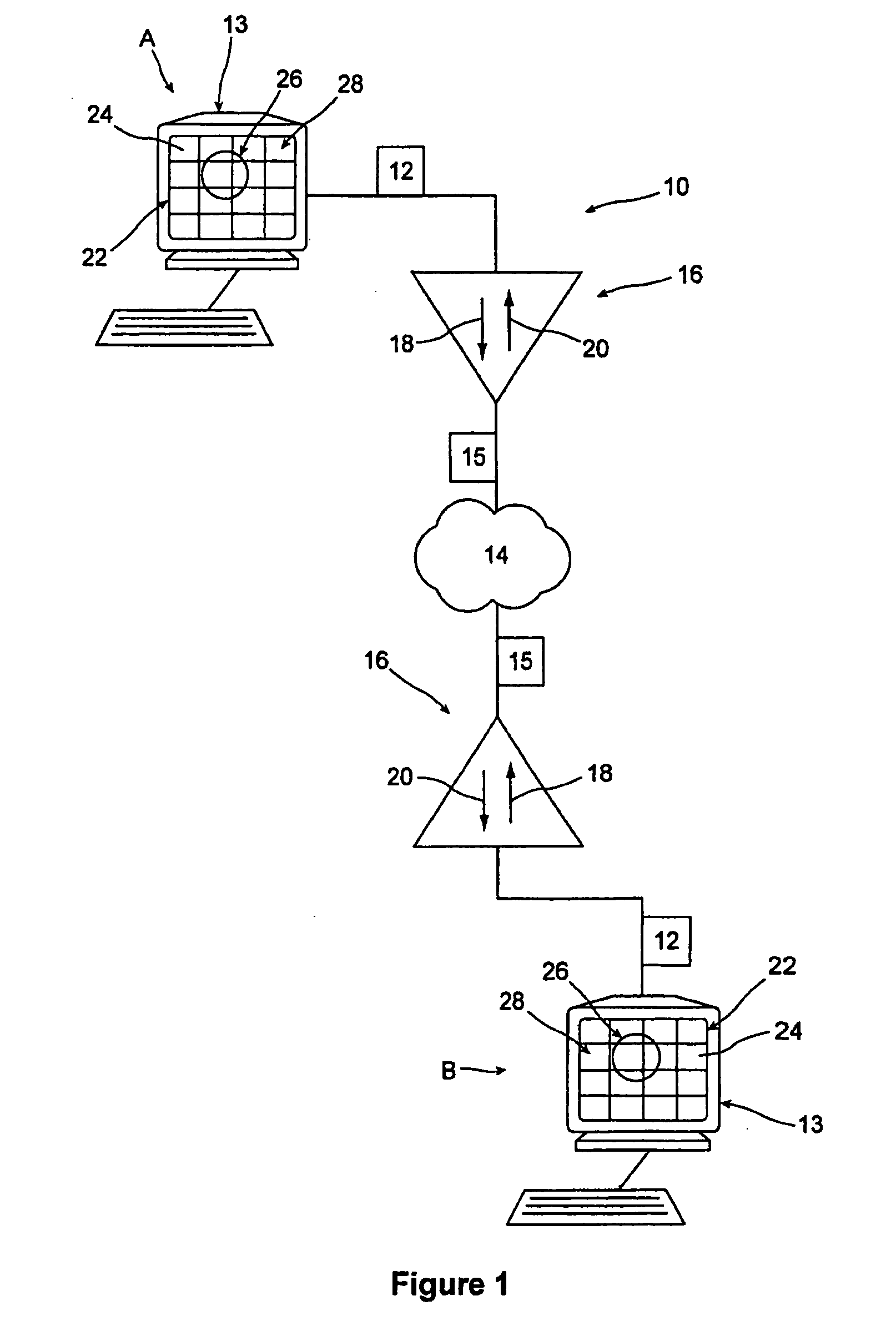
[0054] Referring to FIG. 1, a video conferencing system 10 used as an example of a video transmission system has participants A and B that exchange video data 12 between monitors 13, formatted as a compressed bit stream 15 over a network 14 (such as but not limited to the Internet). Each participant A, B has a video processor 16 having an encoder 18 for encoding transmitted video data 12 and a decoder 20 for decoding the received bit stream 15. Each image frame 22 displayed on the monitors 13 is made of a series of macroblocks 24, such as but not limited to a block of 16×16 pixels, representing (for example) an object 26 which moves over a background 28 (for example a person giving a presentation while standing in front of a backdrop). Accordingly, the processors 16 coordinate the display of successive frames 22 on the monitors 13, as the video data 12 is communicated between the participants A, B, which can include applications such as video conferencing. It will be appreciated rec...


PUM


Abstract

A method of filtering to remove coding artifacts introduced at block edges in a block-based video coder, the method having the steps of: checking the content activity on every line of samples belonging to a boundary to be filtered and where content activity is based on a set of adaptively selected thresholds determined using Variable-Shift Table Indexing (VSTI); determining whether the filtering process will modify the sample values on that particular line based on said content activity; and selecting a filtering mode between at least two filtering modes to apply on a block boundary basis, implying that there would be no switching between the two primary modes on a line by line basis along a given block boundary. The two filtering modes include a default mode based on a non-recursive filter, and a strong filtering mode which features two strong filtering sub-modes and a new selection criterion that is one-sided with respect to the block boundary to determine which of the two strong filtering sub-modes to use. The two strong filtering sub-modes include a new 3-tap filter sub-mode and a 5-tap filter sub-mode that permits a more efficient implementation of the filter.

Description

FIELD OF THE INVENTION [0001] The present invention relates to the field of video coding, more particularly it relates to a method of reducing blocking artifacts inherent in hybrid block-based video coding. BACKGROUND OF THE INVENTION [0002] Video compression is used in many current and emerging products. It has found applications in video-conferencing, video streaming, serial storage media, high definition television (HDTV), and broadcast television. These applications benefit from video compression in the fact that they may require less storage space for archived video information, less bandwidth for the transmission of the video information from one point to another, or a combination of both. [0003] Over the years, several standards for video compression have emerged, such as the Telecommunication Standardization Sector of the International Telecommunication Union (ITU-T) recommended video-coding standards: H.261, H.262, H.263 and the emerging H.264 standard and the International...

Claims


Application Information

Patent Timeline
IPC IPC(8): H04N7/12H04N7/26
CPCH04N19/159H04N19/176H04N19/86H04N19/14H04N19/117
Inventor JOCH, ANTHONYAU, JAMESLIN, YU-SHENG BRANDON
Owner CISCO SYST CANADA
Learn More