Forming and bonding of flex circuits to structures

a technology of flexible circuits and structures, applied in the field of flexible electric circuits, can solve the problems of high signal loss, high cost of thicker material materials, and general acceptance of commercially available flexible circuits with adhesive backings, and achieves the effects of reducing cracking, reducing cracking, and reducing cracking

Active Publication Date: 2006-05-18
THE BOEING CO
View PDF12 Cites 0 Cited by
  • Summary
  • Abstract
  • Description
  • Claims
  • Application Information

AI Technical Summary

Benefits of technology

[0009] An apparatus and method for forming and bonding of flexible circuits to metal structures of the present invention provides several advantages. By clamping an adhesively backed flexible circuit to the metal structure, a repeatable and accurate bond can be formed. By closely controlling a shape of the clamp and a receiving flexible roller fixture, the bending radius of the flexible circuit is controlled to reduce cracking. By using flexible polymeric material for rollers of the roller fixture, the flexible circuits can be rolled with minimal cracking. A clamp frame of the present invention having a predefined or finished shape of the metal structure formed thereon eliminates spring-back of the flexible circuit following bending by the roller fixture and holds the flexible circuit against the metal structure during a subsequent heat curing process to improve the bond of the flexible circuit to the metal structure.

Problems solved by technology

The material of these flexible circuits is more expensive in the thicker material form necessary for use when greater separation of metallization lines for alternating current or radio frequency or higher frequency signals are transferred.
For example, the dielectric constant of KAPTON® material when metallization circuitry lines are closely laid for use in high frequency applications is particularly undesirable and produces higher signal loss.
Commercially available flexible circuits having an adhesive backing are generally unacceptable when formed and bonded to relatively small radii multi-conductor modules such as for phased array antenna applications.
Commercially available multi-layer flexible circuits are also generally unacceptable for higher frequency use.
When multi-layer flexible circuits are required, known systems suffer from cracking and signal crosstalk problems when used or bent to radii needed for the higher frequency small bend radii applications discussed above.

Method used


Image

  • Forming and bonding of flex circuits to structures
  • Forming and bonding of flex circuits to structures
  • Forming and bonding of flex circuits to structures

Examples


Embodiment Construction

[0019] The following description of the preferred embodiments is merely exemplary in nature and is in no way intended to limit the invention, its application, or uses.

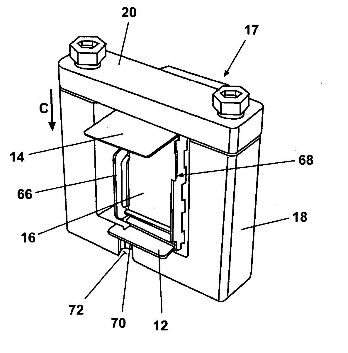
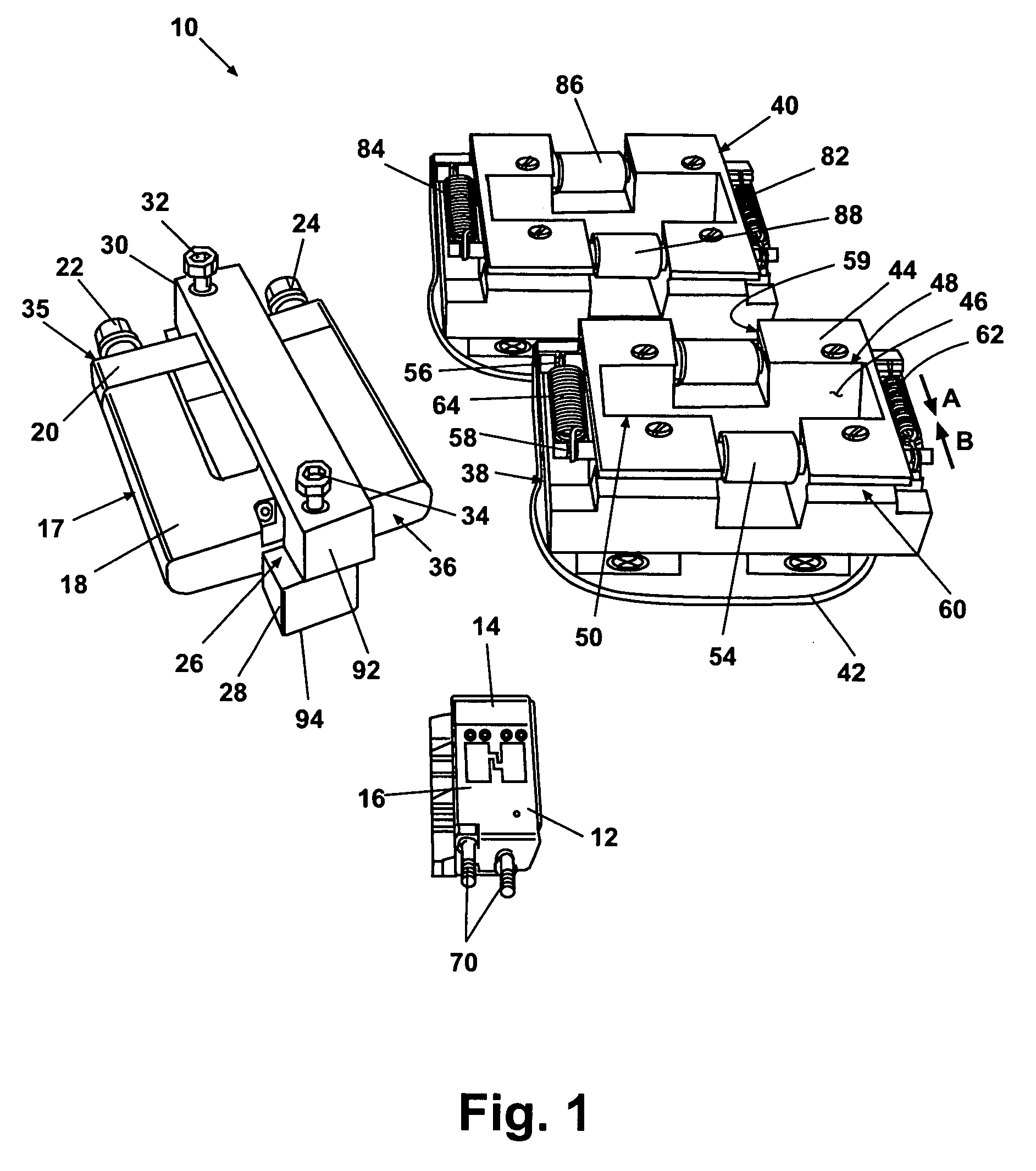
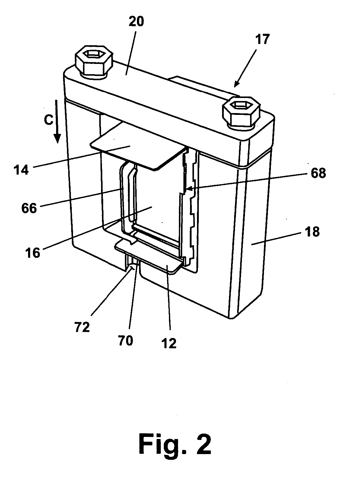
[0020] According to a preferred embodiment of the present invention and generally referring to FIG. 1, a flexible circuit forming apparatus 10 for forming and bonding of flexible circuits to structures is operable to form a first flexible circuit 12 and a second flexible circuit 14 about a mandrel 16. Mandrel 16 can have multiple shapes and provides an exemplary envelope for supporting at least the first flexible circuit 12 and optionally the second flexible circuit 14. In one embodiment, mandrel 16 is an element of a phased array antenna module.

[0021] Mandrel 16 is clamped within a clamping frame 17 during the various processes of the present invention. Clamping frame 17 includes a U-shaped clamping member 18 which generally holds the mandrel 16 within it, and a clamping bar 20, which is fastenably connected to U-sh...


PUM

PropertyMeasurementUnit
thicknessaaaaaaaaaa
thicknessaaaaaaaaaa
thicknessaaaaaaaaaa

Abstract

An apparatus and method for forming and bonding of flexible circuits to metal structures includes a clamping frame having a removable frame portion. At least one flexible roller fixture provides opposed flexible rollers. A clearance aperture in the roller fixture is sized to slidably receive the clamping frame. As the clamping frame is inserted through the clearance aperture of the roller fixture the opposed flexible rollers apply a continuous pressure to deflect the flexible circuit. A curing clamp is then connected to the clamping frame having at least one engagement face defining a flexible circuit finished shape. The flexible circuit is then heat cured to adhesively bond to the metal structure.

Description

GOVERNMENT RIGHTS [0001] This invention was made with government support provided by DUST / USAT under the terms of Contract No. USAT #N6601-99-C-6001. The government has certain rights in the invention.FIELD OF THE INVENTION [0002] The present invention relates in general to flexible electric circuits and more specifically to a device and method for forming and bonding flexible circuits to structures. BACKGROUND OF THE INVENTION [0003] Flexible circuits of various designs are known, in particular for low frequency or direct current applications. For example, commercially available flexible circuit strips such as used for computer printers are generally available in polyimide material film form such as KAPTON® material. A material strip thickness of approximately 0.005 cm (0.002 in) and ranging up to a commercially available 0.013 cm (0.005 in) is known. These flexible circuit strips are generally good for direct current applications where, due to repeated flexing, some cracking of th...

Claims


Application Information

Patent Timeline
Patent Type & Authority Applications(United States)
IPC IPC(8): H01R12/24
CPCH05K1/0393H05K3/0014H05K3/0058H05K3/386Y10T156/1049H05K2203/302H01R12/59Y10T156/1051Y10T156/1028H05K2203/068
Inventor NAVARRO, JULIOBOSTWICK, RICHARD N.BOLSTER, MARK S.
Owner THE BOEING CO
Why Eureka
Try Eureka