
Sintered ceramic, slide part therefrom, and process for producing sintered ceramic

a technology of sintered ceramics and slide parts, applied in the direction of shafts, bearings, mechanical equipment, etc., can solve the problems of reducing the service life of the shaft, abnormal wear, and increasing the friction coefficient, and achieves excellent sliding properties, minimal cracking, and dense structure

Active Publication Date: 2012-10-23
JFC MATERIALS CO LTD
View PDF18 Cites 0 Cited by
  • Summary
  • Abstract
  • Description
  • Claims
  • Application Information

AI Technical Summary

Benefits of technology

"The present invention relates to a ceramic sintered body, a process for producing it, and sliding parts that use it. The ceramic sintered body has a dense structure and minimal cracking, and it can exhibit excellent sliding properties even in a non-lubricated state. It contains a small amount of solid lubricant and has a frictional coefficient that is significantly reduced when the amount of solid lubricant is increased or the particle size of the solid lubricant is increased. The ceramic sintered body is also more resistant to seizing and wear than conventional silicon carbide sintered bodies. The process for producing it involves adding carbon materials to silicon carbide powder and sintering it at high pressure. The resulting ceramic sintered body has low friction and excellent sealing properties. It can be used as a mechanical seal or in other applications where low friction and excellent sliding properties are required."

Problems solved by technology

However in the complete absence of liquid films on sliding surfaces or with inadequate formation of liquid films, (this will hereinafter be referred to as “non-lubricated state”), they create solid friction and have therefore tended to cause seizing of sliding surfaces and abnormal wear as a result, when the frictional coefficient is notably increased.
Consequently, pure sintered silicon carbides have not necessarily been satisfactory in terms of sliding properties and are less than optimal for use in a non-lubricated state.

Method used


Image

  • Sintered ceramic, slide part therefrom, and process for producing sintered ceramic
  • Sintered ceramic, slide part therefrom, and process for producing sintered ceramic
  • Sintered ceramic, slide part therefrom, and process for producing sintered ceramic

Examples


example 1

[0080]In Step A, 4 parts by weight of artificial graphite with a mean particle size of 30 μm and 3 parts by weight of carbon black with a mean particle size of 43 nm were added to 100 parts by weight of silicon carbide powder with a mean particle size of 0.7 μm. There were further added 0.6 part by weight of boron carbide as a sintering aid, 2 parts by weight of a phenol resin in terms of carbon, 3 parts by solid weight of polyvinyl alcohol as a binder and 0.6 part by weight of polyethylene glycol (polymerization degree: #400). A starting mixture was thus obtained.

[0081]In Step E, the compact was sintered at 2190° C.

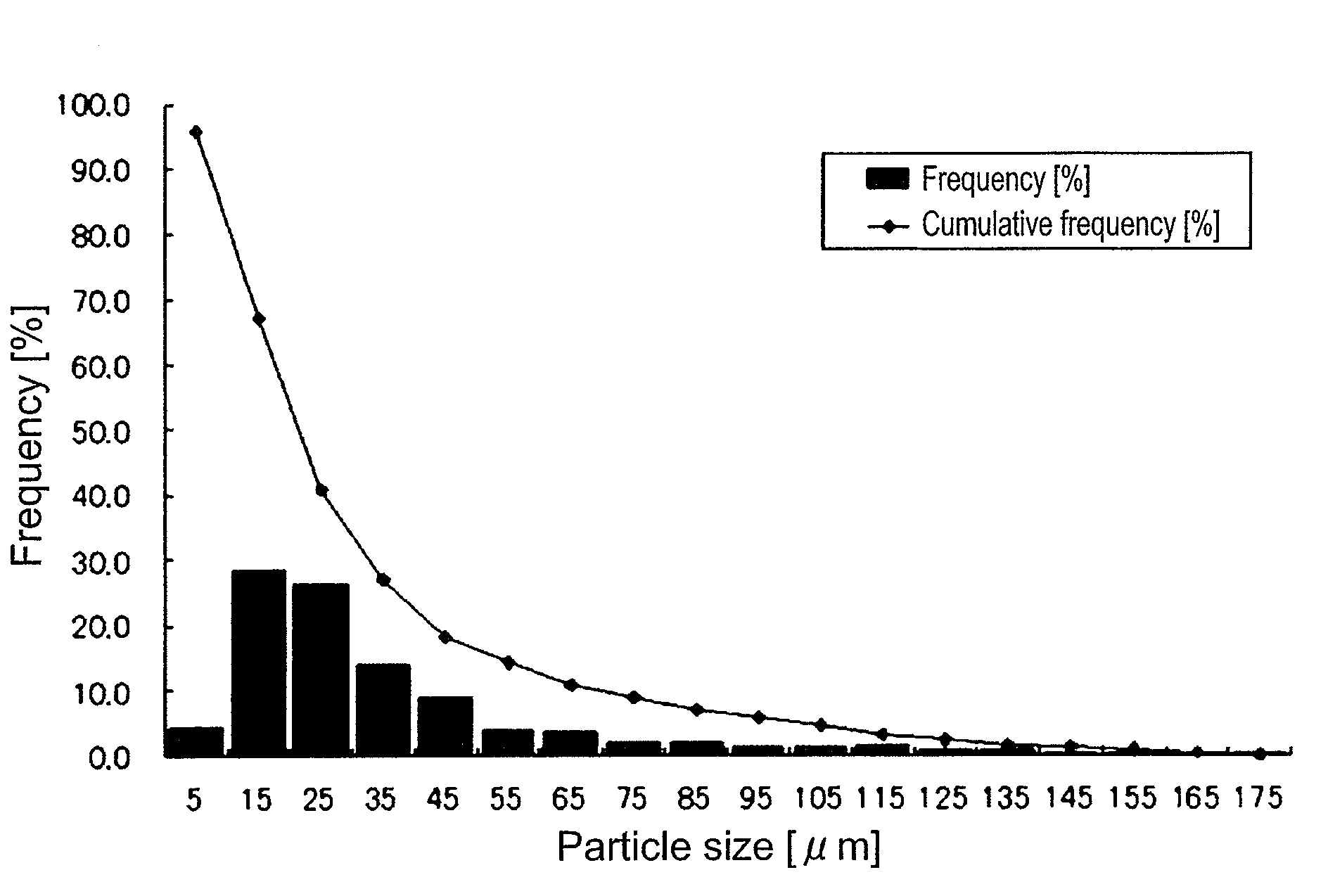
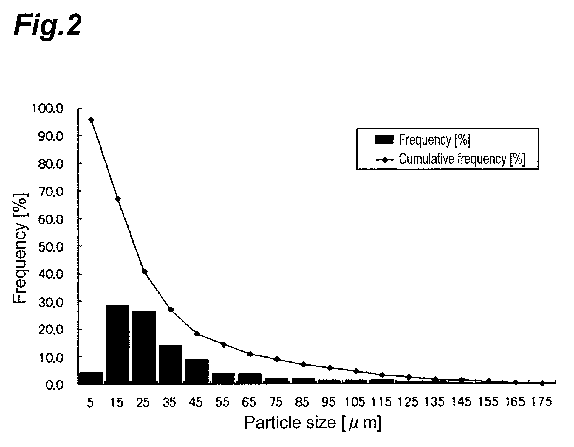
[0082]No cracking was found upon observing the obtained sintered body. Also, as a result of observing the structure of fractured and lapped surfaces of the sintered body, graphites with two different mean particle sizes, 2 μm and 30 μm, were found in the silicon carbide parent material.

example 2

[0083]In Step A, 6 parts by weight of artificial graphite with a mean particle size of 30 μm and 3 parts by weight of carbon black with a mean particle size of 43 nm were added to 100 parts by weight of silicon carbide powder with a mean particle size of 0.7 μm. There were further added 0.6 part by weight of boron carbide as a sintering aid, 2 parts by weight of a phenol resin in terms of carbon, 3 parts by solid weight of polyvinyl alcohol as a binder and 0.6 part by weight of polyethylene glycol (polymerization degree: #400). A starting mixture was thus obtained.

[0084]In Step E, the compact was sintered at 2200° C.

[0085]No cracking was found upon observing the obtained sintered body. Also, as a result of observing the structure of fractured and lapped surfaces of the sintered body, graphites with two different mean particle sizes, 2 μm and 30 μm, were found in the silicon carbide parent material.

example 3

[0086]In Step A, 3 parts by weight of artificial graphite with a mean particle size of 50 μm and 4 parts by weight of carbon black with a mean particle size of 43 nm were added to 100 parts by weight of silicon carbide powder with a mean particle size of 0.7 μm. There were further added 0.6 part by weight of boron carbide as a sintering aid, 2 parts by weight of a phenol resin in terms of carbon, 3 parts by solid weight of polyvinyl alcohol as a binder and 0.6 part by weight of polyethylene glycol (polymerization degree: #400). A starting mixture was thus obtained.

[0087]In Step E, the compact was sintered at 2200° C.

[0088]No cracking was found upon observing the obtained sintered body. Also, as a result of observing the structure of fractured and lapped surfaces of the sintered body, graphites with two different mean particle sizes, 2 μm and 50 μm, were found in the silicon carbide parent material.


PUM

PropertyMeasurementUnit
mean particle sizeaaaaaaaaaa
particle sizeaaaaaaaaaa

Abstract

It is an object of the invention to provide a ceramic sintered body that has a dense structure and minimal cracking and that exhibits excellent sliding properties even in a non-lubricated state, as well as a process for its production and sliding parts that employ the same. According to a preferred mode, the sintered body of the invention comprises silicon carbide as the parent material and further contains a solid lubricant A with a mean particle size of no greater than 5 μm and a solid lubricant B with a mean particle size of 10-70 μm.

Description

TECHNICAL FIELD[0001]The present invention relates to a ceramic sintered body, to sliding parts using it and to a process for production of the ceramic sintered body.BACKGROUND ART[0002]Most sintered silicon carbides are extremely hard and exhibit good lubricity when used with water lubrication, while their wear resistance and chemical resistance are also excellent. They are therefore widely used in sliding parts such as mechanical seals, bearings and the like. For mechanical seal applications, in particular, they may be used even in situations with a high PV value, which represents the product of the contact pressure and rotation rate on the sliding surface, and therefore sintered silicon carbides (silicon carbide ceramics) are considered to be highly useful materials. Moreover, it is well known that sintered silicon carbides can be used with even higher PV values if pores are introduced therein.[0003]Conventional sintered silicon carbides have exhibited satisfactory properties aga...

Claims


Application Information

Patent Timeline
Patent Type & Authority Patents(United States)
IPC IPC(8): C04B35/52C04B35/56C01B31/36
CPCC04B35/565F16C33/043F16J15/3496C04B2235/3821C04B2235/3826C04B2235/424C04B2235/425C04B2235/5436C04B2235/48C04B2235/5445C04B2235/668C04B2235/767C04B2235/77F16C33/24
Inventor AKASAKA, KAZUYUKIKAWAI, KIYOSHI
Owner JFC MATERIALS CO LTD
Learn More