System and method for developing ultra-sensitive microwave and millimeter wave phase discriminators

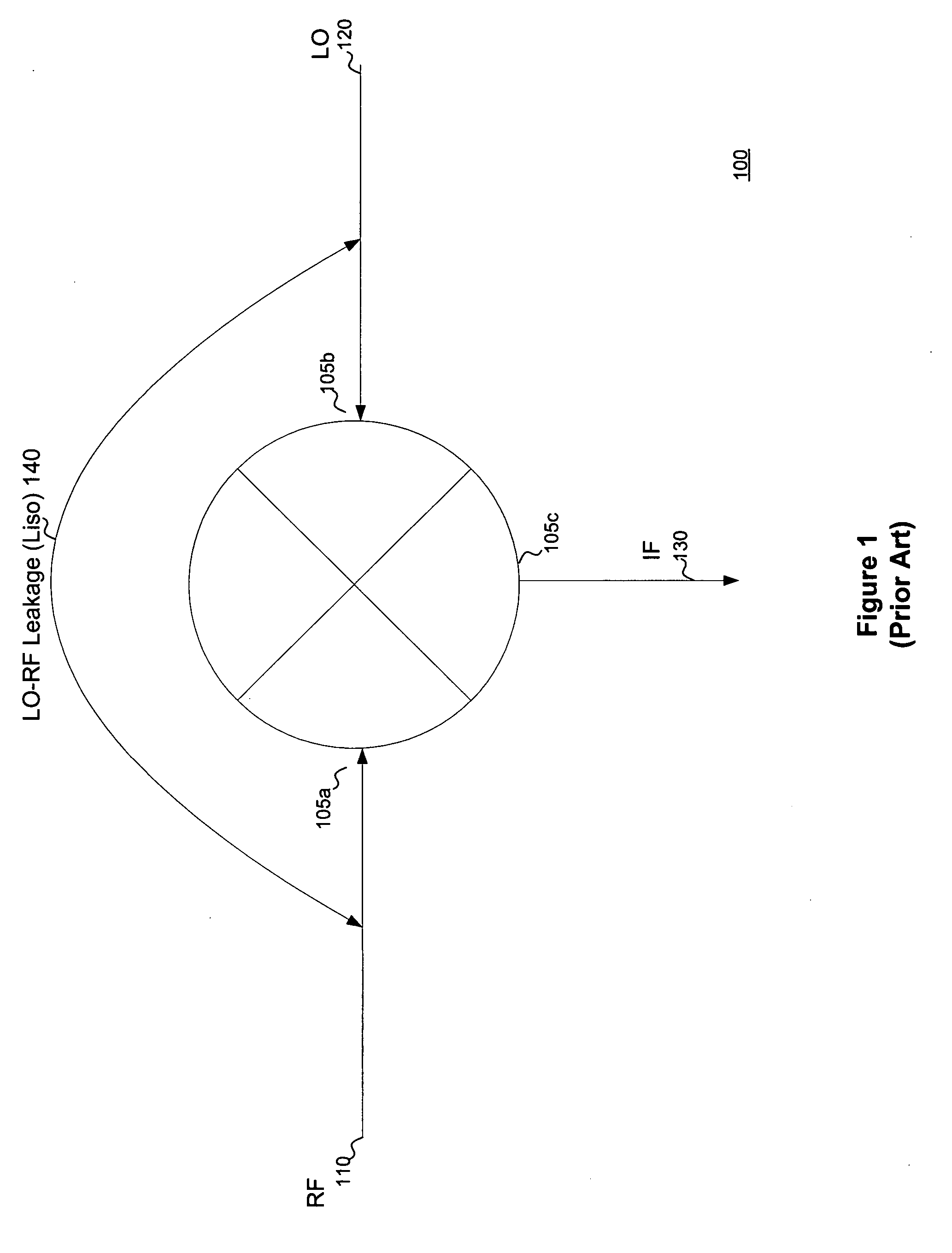
a phase discriminator, ultra-sensitive technology, applied in oscillator comparator circuits, modulation transference by distributed inductance and capacitance, electrical devices, etc., can solve the problem of part of the lo signal leaking into the rf port, particularly susceptible to leakage, and increase leakage. problem, to achieve the effect of improving lo-rf isolation and improving sensitivity

Inactive Publication Date: 2006-05-18
HONEYWELL INT INC
View PDF11 Cites 15 Cited by
  • Summary
  • Abstract
  • Description
  • Claims
  • Application Information

AI Technical Summary

Benefits of technology

[0015] The present invention relates to a phase discriminator having increased LO-RF isolation to improve sensitivity. The phase discriminator includes a first coupler for receiving an input reference signal and dividing the input reference signal into a first reference signal and a second reference signal. The second reference signal is of equal magnitude to the first reference signal but is shifted in phase by 90 degrees from the first reference signal.

Problems solved by technology

Microwave and millimeter wave phase discriminators are particularly susceptible to problems with leakage because of the high frequencies involved.
As frequency increases, LO-RF isolation decreases, which results in leakage increases.
Finite isolation causes a part of the LO signal to leak into the RF port.
Because this DC offset provides a barrier the RF signal must overcome to be detectable, it is undesirable because it reduces sensitivity.
Both solutions are undesirable because either the overall power consumption of the system increases or the radar range is limited.
Moreover, using a low noise amplifier (“LNA”) to amplify RF signal 110 before it is input into mixer 100 may not increase the signal strength sufficiently to overcome the effect of LO leakage.
Although it is possible in theory to cascade LNAs together to achieve the required overall 60 to 70 dB gain, such an approach is generally not practical due to the problem of oscillations.
Thus, for microwave and millimeter wave applications the use of a LNA does not provide an effective solution.

Method used


Image

  • System and method for developing ultra-sensitive microwave and millimeter wave phase discriminators
  • System and method for developing ultra-sensitive microwave and millimeter wave phase discriminators
  • System and method for developing ultra-sensitive microwave and millimeter wave phase discriminators

Examples


Embodiment Construction

[0022] Embodiments of the present invention include systems and methods for reducing or eliminating the DC offset voltage resulting from leakage between an LO port and an RF port. Embodiments of the present invention use a unique passive circuit technique to reduce or eliminate RF leakage, thereby dramatically increasing overall mixer sensitivity. Moreover, this technique can be implemented in hybrid as well as monolithic microwave integrated circuits (“MMIC”).

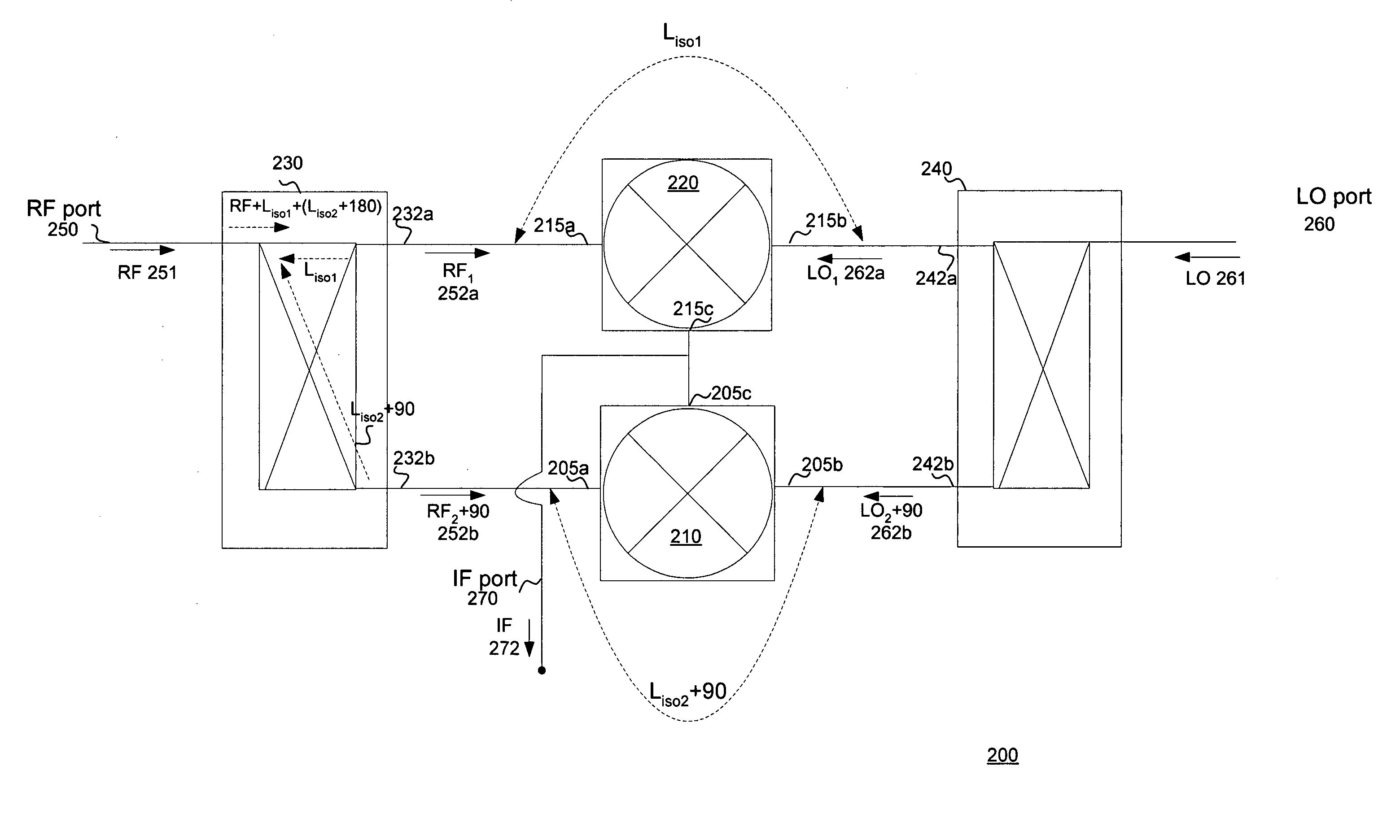
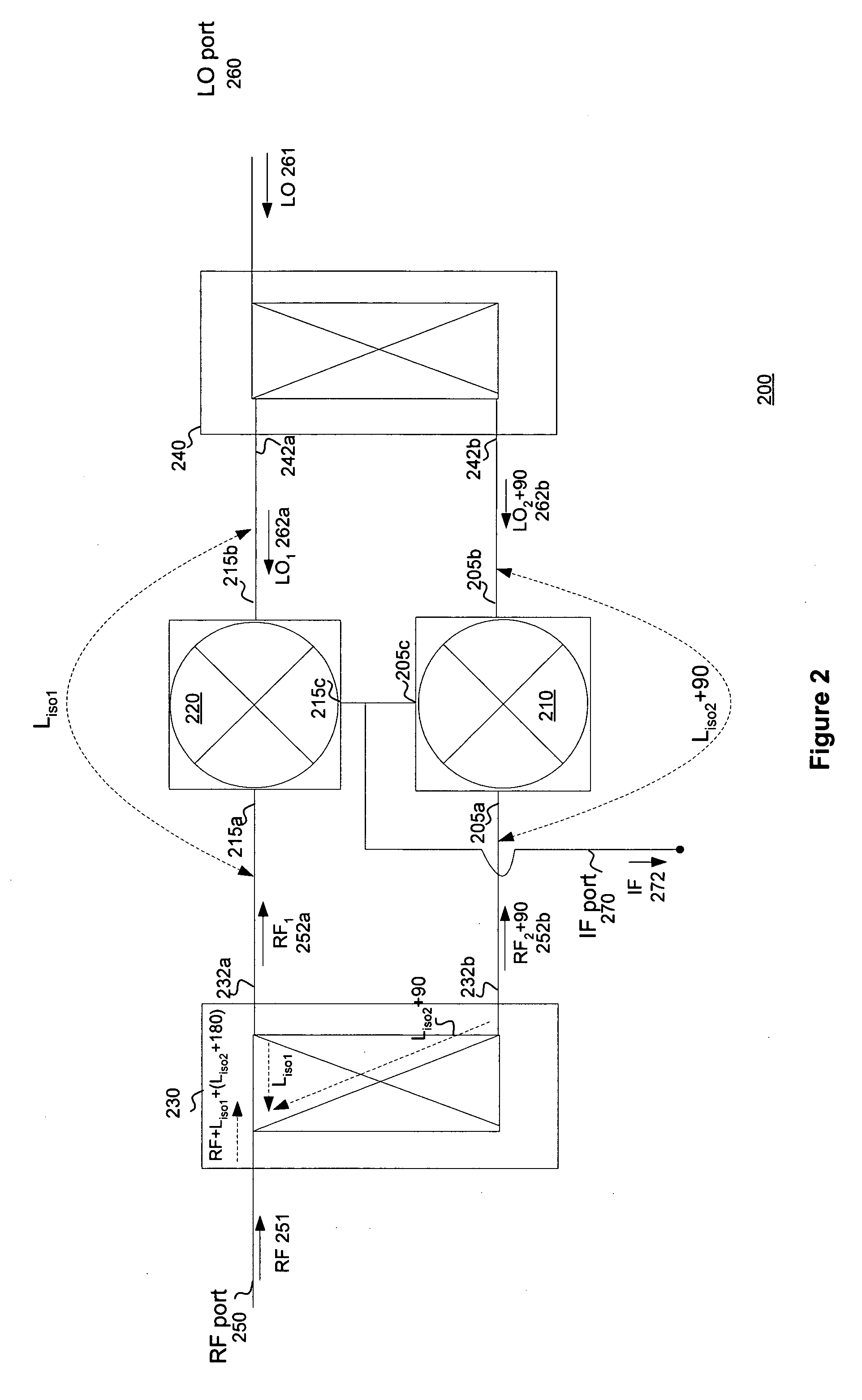
[0023] Particularly, a method is disclosed in which two mixers are inserted between two 3 dB, 90-degree hybrids (couplers). The IF ports of both mixers are connected together to a common port. The LO port coupler divides the LO signal into two equal signals. In addition, the LO port coupler introduces a phase difference of 90 degrees in one of the signals. The LO signals drive the two mixers, and a small portion of each of the signals is channeled as LO-RF leakage to the RF inputs of two mixers. The leakage signals are couple...


PUM


Abstract

A method and system for improving sensitivity of microwave and millimeter phase discriminators is disclosed. An exemplary embodiment of a phase discriminator includes two mixers inserted between two 90 degree hybrids. One hybrid splits the reference or LO signal into two signals of equal magnitude with a phase difference of 90 degrees. Similarly, the other hybrid splits the received RF signal into equal signals shifted 90 degrees in phase. One mixer receives an input set (e.g., LO and RF signals) with a zero-degree phase shift, and the other mixer receives the input set shifted in phase by 90 degrees. Thus, the leakage signals at the output of each mixer have the same magnitude but are 180 degrees apart in phase. The IF ports of the mixers are tied together, allowing the leakage signals of the mixers to combine destructively, thereby increasing isolation and sensitivity.

Description

[0001] This application claims the benefit of U.S. Provisional Application No. 60 / 627,903, filed Nov. 16, 2004, which is herein incorporated by reference in its entirety.[0002] This invention was made with Government support under contract no. DL-8-531322 awarded by the Air Force. The Government has certain rights in the invention.BACKGROUND [0003] 1. Field of the Invention [0004] The present invention relates generally to phase discriminators. More specifically, the present invention relates to developing ultra-sensitive microwave and millimeter wave phase discriminators. [0005] 2. Background of the Invention [0006] Microwave and millimeter wave phase discriminators are used in numerous applications to detect and measure the relative phase of a received microwave or millimeter signal that has been frequency or phase modulated. These applications include radar and communications, proximity sensors and in recently emerging applications involving accelerometers. [0007] Most systems wh...

Claims


Application Information

Patent Timeline
Patent Type & Authority Applications(United States)
IPC IPC(8): H04B1/10
CPCH03D9/06H03D13/007H03D2200/0047H03D2200/0082H03D2200/009
Inventor SINGH, DONALD R.CARLSON, DOUGLAS R.
Owner HONEYWELL INT INC
Why Eureka
Try Eureka