
Photodynamic therapy light source

a light source and photodynamic therapy technology, applied in the field of photodynamic therapy light sources, can solve the problems of increasing the difficulty of providing records of treatment and also of the success or progress of a treatment strategy, and the entire patient's body was subjected to poforins, so as to improve the effectiveness of treatment and achieve better results.

Inactive Publication Date: 2006-05-18
ROFIN AUSTRALIA PTY LTD
View PDF10 Cites 21 Cited by
  • Summary
  • Abstract
  • Description
  • Claims
  • Application Information

AI Technical Summary

Benefits of technology

[0078] The sequence of illumination according to this aspect of the invention has been found to enhance the effectiveness of the treatment compared to a continuous “on” light protocol in which light is always applied to the patient. This is because the modulation which provides periods of illumination then periods when no illumination is applied, changes the deposition of energy and then relaxation which in turn has been found to produce better results in some patients and in some types of treatment.

Problems solved by technology

Conventional light sources which are used in photodynamic therapy are not particularly flexible and generally are used to address only a single radiation bandwidth.
The conventional systems also do not provide any feedback in relation to the treatment process or progress made by a patient, thereby increasing the difficulty of providing records of treatment and also of the success or progress of a treatment strategy.
This procedure had the disadvantage that the poforins were injected into a patient and therefore, the entire patient's body was subjected to the poforins.

Method used


Image

  • Photodynamic therapy light source
  • Photodynamic therapy light source
  • Photodynamic therapy light source

Examples


Embodiment Construction

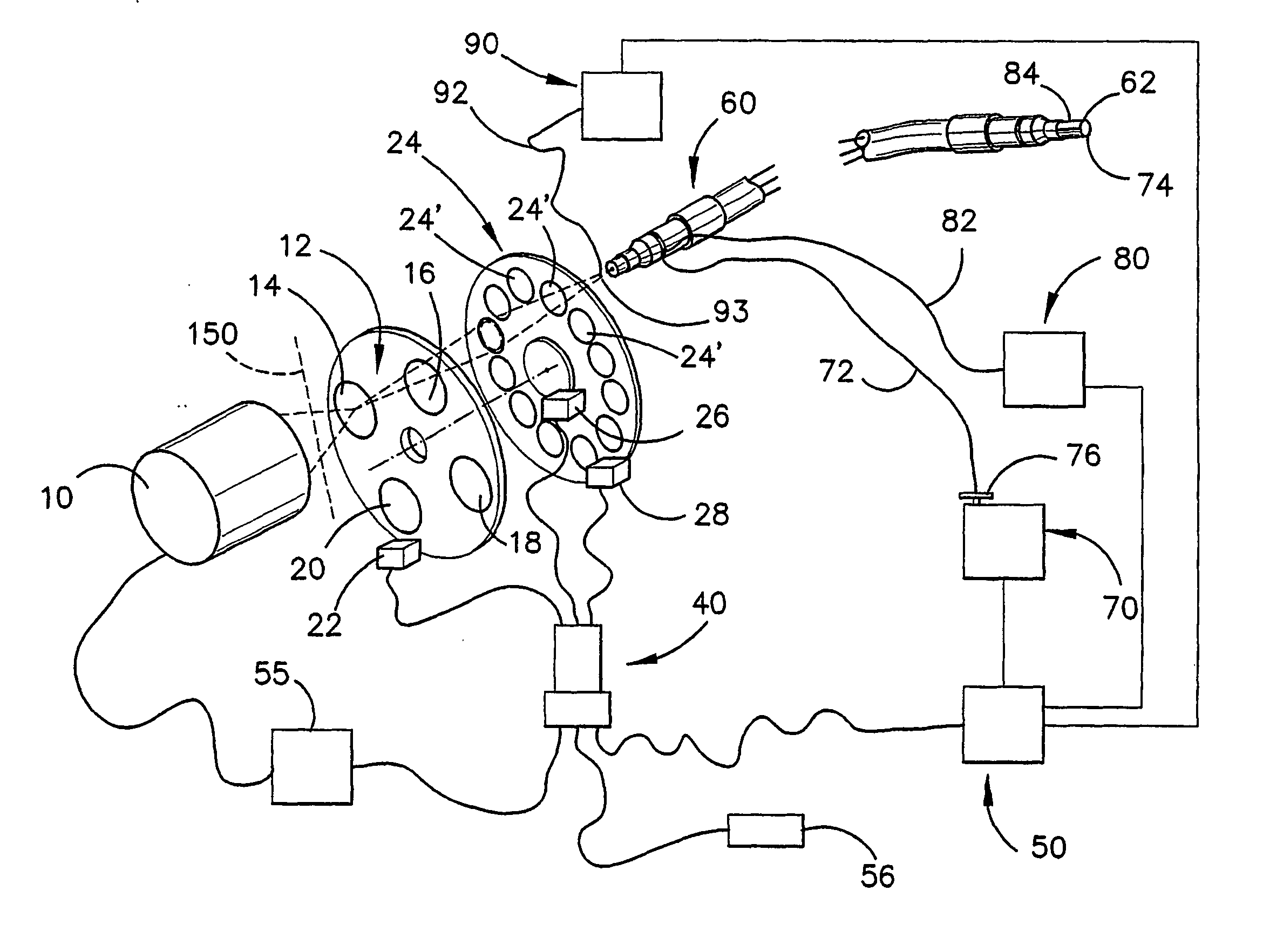
[0103] With reference to FIG. 1, the photodynamic therapy light source is shown in schematic form. The photodynamic therapy light source includes a light source 10 for providing illumination. The light source may be a lamp of any suitable design for providing illumination across a relatively wide bandwidth, including at least the UV spectrum, visible light spectrum and the infrared spectrum.

[0104] A primary filter wheel 12 is provided which has four filter elements 14, 16, 18 and 20. The filter element 14 is in the form of a mirror which effectively reflects UV radiation but allows white light or light in the visible spectrum to pass, the element 16 removes the visible part of the spectrum and enables ultraviolet light to pass, the filter element 18 allows the visible spectrum to pass, and the element 20 is effectively a blank, which prevents any radiation from the light source 10 from passing through the filter wheel 12. The filter wheel 12 has a drive motor 22 for rotating the fi...


PUM


Abstract

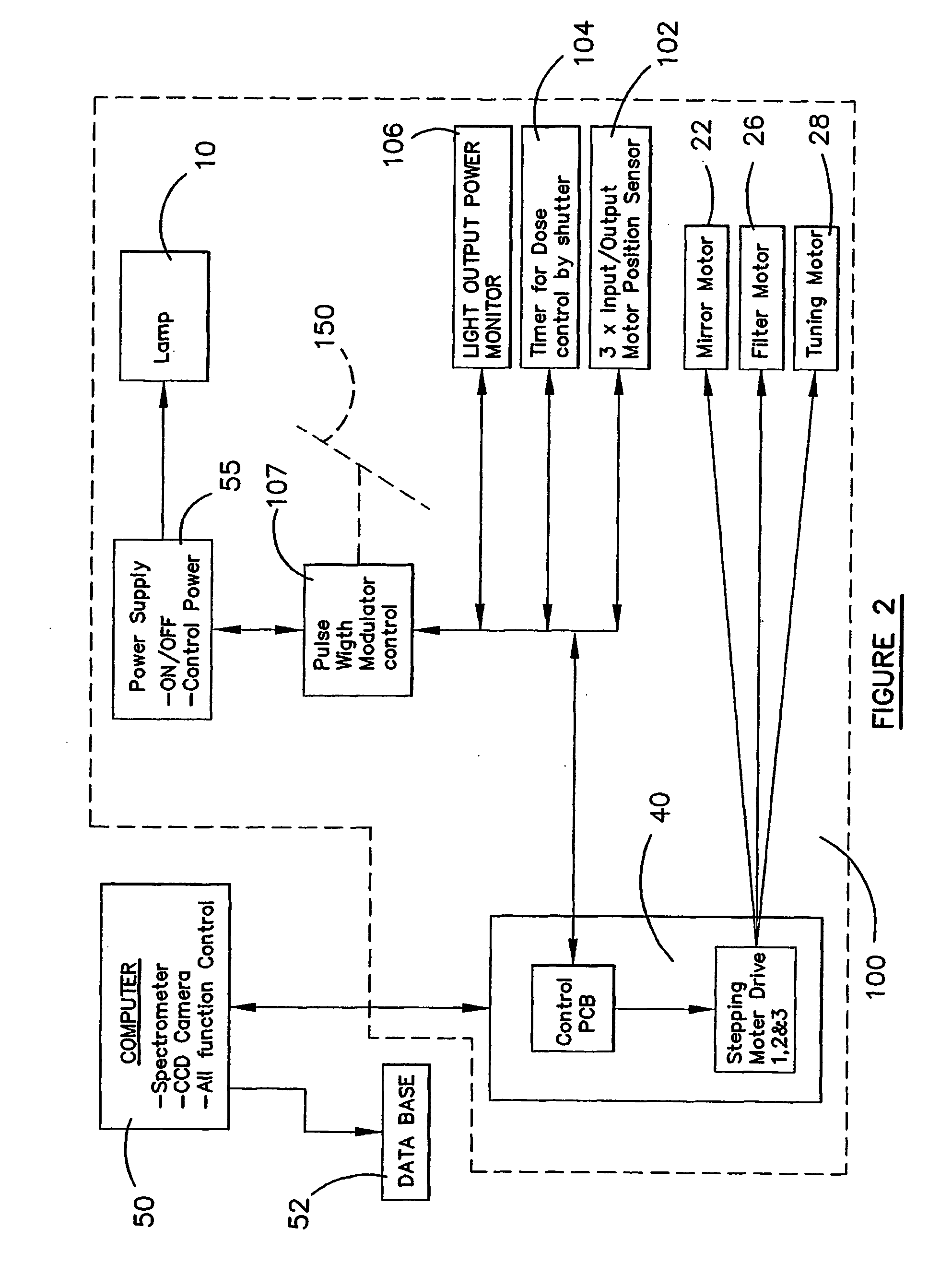
A photodynamic therapy light source for treating skin conditions of a patient is disclosed which has a light source (10), a filter wheel (24), a light guide (60), and a control unit (40) for controlling the source. A spectral analyser (80) is included for analysing the spectrum received from a patient, and a camera (70) is also provided for taking images of the patient so that before and after treatment images can be taken for comparison purposes and for further diagnosis. A filter wheel (24) is provided which includes a number of filter elements (24′) for selectively enabling a particular bandwidth of illumination to be provided. The illumination from the unit (10) can be modulated so that a cyclic treatment of a period in which illumination is applied, followed by a period in which illumination is not applied is provided. The period in which illumination is applied can be further pulsed or modulated to provide a pulsed illumination to the patient during the period in which illumination is applied to the patient.

Description

FIELD OF THE INVENTION [0001] This invention relates to a photodynamic therapy light source for treating skin conditions of a patient. BACKGROUND ART [0002] Photodynamic therapy basically comprises the application of light of a particular wavelength to a patient's skin in order to repair damage, destroy unwanted cells or to provide information enabling diagnosis of various skin conditions. [0003] Conventional light sources which are used in photodynamic therapy are not particularly flexible and generally are used to address only a single radiation bandwidth. The conventional systems also do not provide any feedback in relation to the treatment process or progress made by a patient, thereby increasing the difficulty of providing records of treatment and also of the success or progress of a treatment strategy. [0004] In one specific prior art form of treatment, poforins, which are a breakdown component of red blood cells, were administered to a patient in order to attempt to identify ...

Claims


Application Information

Patent Timeline
IPC IPC(8): A61N5/06A61B5/103
CPCA61B5/0059A61B5/444A61N5/0616A61N5/062
Inventor FRAVAL, HADRIAN NICHOLAS
Owner ROFIN AUSTRALIA PTY LTD
Learn More