Method and apparatus for reliably placing and adjusting a left ventricular pacemaker lead

a left ventricular and lead technology, applied in the direction of internal electrodes, transvenous endocardial electrodes, therapy, etc., can solve the problems of microemboli formation, decreased blood flow, and obstruction of the normal flow of blood in the transvenous cardiac lead, so as to improve the anchoring and positioning of the electrode

Inactive Publication Date: 2006-05-18
WOOLLETT IAN
View PDF3 Cites 41 Cited by
  • Summary
  • Abstract
  • Description
  • Claims
  • Application Information

AI Technical Summary

Benefits of technology

[0010] In this regard, the present invention provides for a novel left ventricular stimulation lead construction and a technique for lead placement that provides for imp...

Problems solved by technology

Even now, due to difficulties and limitations of the coronary sinus approach, it is often necessary to surgically implant a pacing lead after a failed transvenous attempt.
Further, there have always been tradeoffs associated with the usage of transvenously placed leads in many patients.
For example, like any foreign body introduced into the cardiovascular system, a transvenous cardiac lead presents an obstruction to the normal flow of blood.
This obstruction can potentially interfere with the normal operation of one or more of the valves of the heart and may result in not only a diminished blood flow, but also may lead to the formation of microemboli.
The difficulty with this type of lead and the traditional “over-the-wire” placement method is that it is often difficult to properly anchor the lead into the desired location in one of the coronary venous branches.
In particular, once the guide wire is removed, the potential exists for the lead to drift or draw back along the vessel into which it ...

Method used


Image

  • Method and apparatus for reliably placing and adjusting a left ventricular pacemaker lead
  • Method and apparatus for reliably placing and adjusting a left ventricular pacemaker lead
  • Method and apparatus for reliably placing and adjusting a left ventricular pacemaker lead

Examples


Embodiment Construction

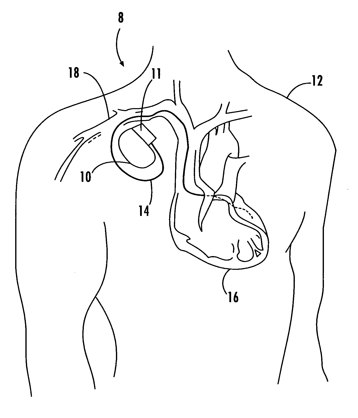
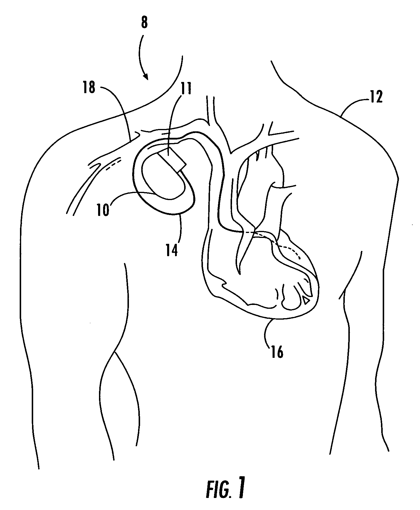
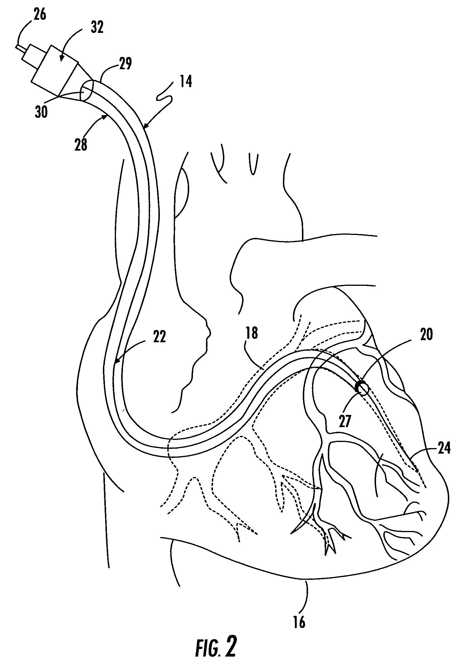
[0023] Now referring to the drawings, as was stated above, the present invention provides for a novel left ventricular stimulation lead construction and a technique for lead placement that provides for improved anchoring and positioning of the electrode located on the distal end of the lead, while also including a method for readjusting the positioning of the lead as necessary. It can be appreciated by one skilled in the art of implantable medical devices that, while embodiments of the present invention are described herein in the context of an epicardial implant via a cardiac vein, embodiments of the present invention may be implemented in a host of other therapy delivery contexts.

[0024] The present invention is directed to a lead that is implanted through a cardiac venous system, such as the coronary sinus and its tributaries and is utilized to stimulate, defibrillate, and / or sense the atrium and ventricle of the left side of the heart. As was stated above, in the prior art it ...


PUM


Abstract

A left ventricular stimulation lead construction and a technique for lead placement that provides for improved anchoring and positioning of the electrode located on the distal end of the lead, while also including a method for readjusting the positioning of the lead as necessary. The lead includes a small diameter guide wire wherein the distal end of the guide wire serves as an anchor for the pacing lead. The lead structure includes a central hollow lumen to allow passage of the guide wire and a locking mechanism positioned on the proximal end of the pacing lead to fix the ends of the guide wire and pacing lead relative to one another. The method provides for advancing the guide wire until it is anchored, positioning the pacing lead along the guide wire into the desired position relative to the cardiac tissue, releasably fixing the lead relative to the guide wire, wherein the guide wire is permanently retained to serve as an anchor.

Description

CROSS-REFERENCE TO RELATED APPLICATIONS [0001] This application is related to and claims priority from earlier filed U.S. Provisional Patent Application No. 60 / 628,444, filed Nov. 16, 2004, the contents of which are incorporated herein by reference.BACKGROUND OF THE INVENTION [0002] The present invention relates generally to a new apparatus and method for the placement of a left ventricular stimulation lead via the coronary sinus and associated branches of the cardiac venous system. More specifically, the present invention relates to a unique lead construction that includes an integrated guide wire, wherein the guide wire is permanently retained in position to allow accurate placement of the lead, improved anchoring of the lead and the ability to readjust lead positioning as necessary to avoid diaphragmatic pacing stimulation and to achieve the optimal pacing site for hemodynamic benefit. [0003] It is common in the healthcare related field to utilize electrical stimulation of body t...

Claims


Application Information

Patent Timeline
IPC IPC(8): A61N1/05
CPCA61N1/056A61N2001/0585
Inventor WOOLLETT, IAN
Owner WOOLLETT IAN
Why Eureka
Try Eureka