Flow reducing implant

a technology arteries, applied in the field of flow reducing implants, can solve the problems of reducing heart output, occlusion of coronary arteries, further damage beyond, etc., and achieves the effects of reducing ischemia and/or its crippling sequela, promoting angiogenesis, and reducing blood flow

Inactive Publication Date: 2006-05-18
NEOVASC MEDICAL LTD
View PDF99 Cites 128 Cited by
  • Summary
  • Abstract
  • Description
  • Claims
  • Application Information

AI Technical Summary

Benefits of technology

[0031] An aspect of some embodiments of the invention relates to a percutaneously deliverable flow reducing implant that reduces blood flow in the coronary sinus. In an exemplar

Problems solved by technology

Occlusion of coronary arteries is a leading cause of death, especially sudden death, in what is commonly called a “heart attack”.
As the activity of the heart is mediated by electrical signal propagation, such disruption typically propagates to the rest of the heart, disorganizes the heart's activation and causes the heart output to be reduced drastically, which leads to ischemia and further damage beyond what was caused directly by the blockage.
If a patient survives the direct effects of the heart attack, the damage to the heart may predispose the patient to future electrical disorders and/or may significantly reduce the coronary output, thus reducing quality of life and life expectancy.
Increased blood flow is required by the heart during exertion, but occluded arteries cannot provide the required increase in flow.
The resultant ischemia produces pain, referred to as angina pectoris, that is not in itself life-threatening but may significantly reduce the quality o

Method used


Image

  • Flow reducing implant
  • Flow reducing implant
  • Flow reducing implant

Examples


Embodiment Construction

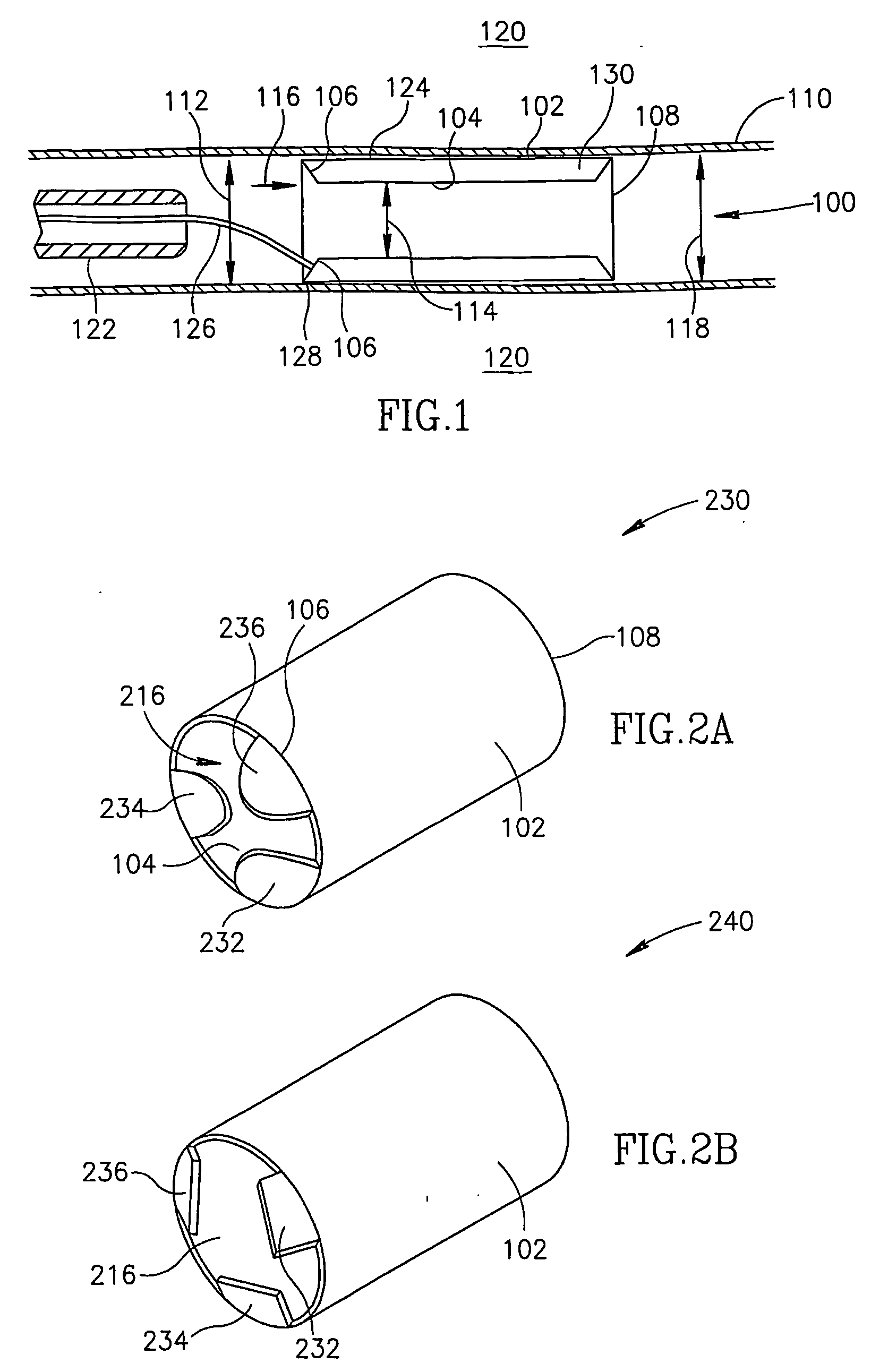
[0075]FIG. 1 is a longitudinal section of a dual wall type flow reducing implant 100 installed in a coronary sinus 110 with a pre-implant sinus cross section dimension 112, in accordance with an exemplary embodiment of the invention. Flow reducing implant 100 comprises an outer wall 102 and an inner wall 104. At least a portion of outer wall 102 contacts coronary sinus 110. At least a portion of inner wall 104 is separated from outer wall 102 by a space 130 and defines a flow passage 114 that is narrower in diameter than coronary sinus pre-implant diameter 112.

[0076] Thus, blood flowing in a direction 116 will have a reduced flow upon exiting dual wall flow reducing implant 100 via a rear end 108 into a post implant coronary sinus 118. In reducing blood flow in direction 116, flow reducing implant 100 optionally promotes angiogenesis, for example, in an area of coronary tissue 120.

[0077] In an exemplary embodiment, inner wall 104 and / or outer wall 102 are resilient and dual wall f...


PUM


Abstract

An intra-vascular balloon (110), comprising a balloon body (1010); and at least one springy and elongate stave (1030) attached to said balloon and conforming to a surface of said balloon, such that said stave can apply contact force to an object in contact with said balloon.

Description

RELATED APPLICATIONS [0001] This application is a continuation in part of U.S. application Ser. No. 09 / 534,968, filed Mar. 27, 2000 the disclosure of which is incorporated herein by reference. This application is also a continuation in part of PCT / IL01 / 00284, filed on Mar. 27, 2001 which designates the US and was published as PCT publication WO 01 / 72239 A2 in the English language. This application is also a continuation in part of PCT applications PCT / IL02 / 00805, published as WO 03 / 028522 and PCT / IL03 / 00303, filed Apr. 10, 2003. All of these PCT applications designate the US. [0002] This application also claims priority from the following applications: Israel Application No. 151162, filed on Aug. 8, 2002, Israel Application No. 152366, filed on Oct. 17, 2002 and Israel Application No. 153753, filed on Dec. 30, 2002. [0003] The disclosure of all of the above documents is incorporated herein by reference.FIELD OF THE INVENTION [0004] The present invention relates to devices for reduci...

Claims


Application Information

Patent Timeline
IPC IPC(8): A61F2/06A61F2/84A61F2/82A61B17/12A61F2/00A61F2/91A61F2/915A61F2/95A61F2/958
CPCA61B17/12022A61F2230/008A61B17/12131A61B17/12172A61F2/91A61F2/915A61F2/958A61F2002/068A61F2002/91525A61F2002/91533A61F2002/9155A61F2002/91558A61F2002/9511A61F2250/0039A61F2230/0078A61B17/12036
Inventor BEN MUVHAR, SHMUEL
Owner NEOVASC MEDICAL LTD
Why Eureka
Try Eureka