Pressure-regulating valve, functional liquid supplying apparatus, imaging apparatus, method of manufacturing electo-optic device, electro-optic device, and electronic apparatus

a technology of functional liquid supplying apparatus and pressure regulator, which is applied in the direction of fluid pressure control, process and machine control, instruments, etc., can solve the problems of complicated and inability to replace springs independently, and achieve the effect of simple replacement, convenient replacement, and short period of tim

Active Publication Date: 2006-05-25
SEIKO EPSON CORP
View PDF6 Cites 10 Cited by
  • Summary
  • Abstract
  • Description
  • Claims
  • Application Information

AI Technical Summary

Benefits of technology

[0009] It is an advantage of the invention to provide a pressure-regulating valve in which a valve-disc energizing spring or a negative-pressure holding spring incorporated can be easily replaced, a functional liquid supplying apparatus, an imaging apparatus, a method of manufacturing an electro-optic device, an electro-optic device, and an electronic apparatus.
[0010] According to one aspect of the invention, there is provided a pressure-regulating valve which is interposed between a functional liquid droplet ejection head for ejecting a functional liquid droplet to perform an imaging process on a workpiece and a functional liquid tank for supplying a functional liquid to the functional liquid droplet ejection head, supplies to the functional liquid droplet ejection head through a secondary chamber a functional liquid introduced from the functional liquid tank to a primary chamber, and opens and closes a communication passage for communicating the primary chamber and the secondary chamber using, as a reference regulating pressure, atmospheric pressure which a diaphragm constituting one surface of the secondary chamber and exposed to atmosphere receives. The pressure-regulating valve comprises: a valve housing forming the primary chamber and the secondary chamber; a valve disc for opening and closing the communication passage; and a valve-disc energizing spring for energizing the valve disc in a valve-closing direction, using as a receiver a spring-receiving portion of the valve housing, wherein the valve housing is constituted of a housing main body and a lid body having the spring-receiving portion and detachably attached to the housing main body, and the valve-disc energizing spring is configured so as to be separated from the housing main body along with separation of the lid body.
[0011] According to this configuration, when a functional liquid having a different specific gravity is introduced, the lid body is pulled out from the housing main body, so that the primary chamber is left open to atmosphere and the valve-disc energizing spring can be replaced with one having repulsion corresponding to the specific gravity of the functional liquid. Furthermore, such a replacing operation can cope with features such as corrosion other than specific gravity as well. This is to say that it is only necessary to keep, as replacement parts, common parts which can be commonly used irrespective of the material feature of a functional liquid and corresponding parts so as to correspond to the material feature are prepared in a state that they are prior to being built together. Accordingly, it is not required to, for example, replace the whole pressure-regulating valve, adjust the height of the functional liquid tank and the pressure-regulating valve, or the like.
[0012] In this case, it is preferable that the valve-disc energizing spring and the lid body be linked to each other.
[0013] According to this configuration, when a functional liquid having a different specific gravity is introduced, the valve-disc energizing spring can be detached along with separation of the lid body, thereby making it possible to complete a replacing operation simply and in a short period of time.
[0014] In this case, it is preferable that the valve disc be configured so as to be separated from the housing main body along with separation of the valve-disc energizing spring.

Problems solved by technology

Moreover, the valve-disc energizing spring and the negative-pressure holding spring must be replaced with new ones, because they could be corroded depending on the functional liquid used.
Therefore, the springs cannot be replaced independently, thus the entire pressure-regulating valve must be replaced.
But, such replacing and adjusting operations are liable to make things complicated.

Method used


Image

  • Pressure-regulating valve, functional liquid supplying apparatus, imaging apparatus, method of manufacturing electo-optic device, electro-optic device, and electronic apparatus
  • Pressure-regulating valve, functional liquid supplying apparatus, imaging apparatus, method of manufacturing electo-optic device, electro-optic device, and electronic apparatus
  • Pressure-regulating valve, functional liquid supplying apparatus, imaging apparatus, method of manufacturing electo-optic device, electro-optic device, and electronic apparatus

Examples


first embodiment

[0136] Referring next to FIG. 11, description will be made about a first modified example of the above-described According to the modified example, the valve disc 176 of the invention has a part where the valve disc 176 is engaged with the valve-disc energizing spring 267. At that part is formed a leading-end engaging portion 287 made up of a generally flat spring-receiving portion 285 for receiving the force of the valve-disc energizing spring 267 and a conical convex portion 286 extending from the spring-receiving portion 285 to the valve-disc energizing spring side in a tapered state. The proximal-end portion of the conical convex portion 286 has an external diameter generally the same length as the internal diameter of the valve-disc energizing spring 267. Furthermore, the valve disc has a part where the lid body 190 is engaged with the valve-disc energizing spring 267. At that part is formed a proximal-end engaging portion 290 made up of a generally flat spring-receiving porti...

third embodiment

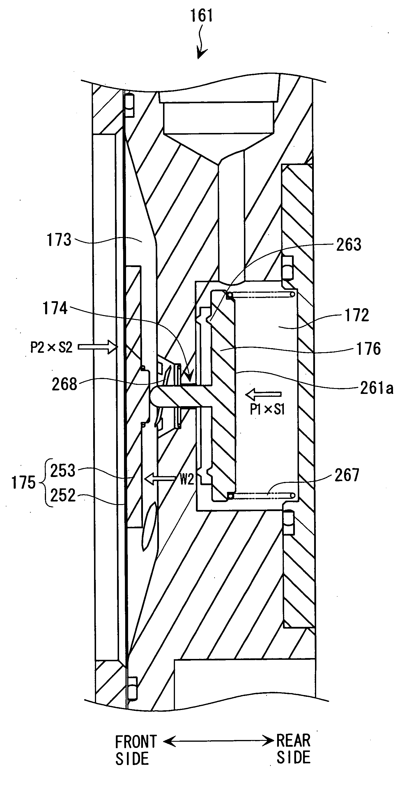
[0144] Referring next to FIGS. 13, 14, and 15, description will be made about the pressure-regulating valve 161 of a The pressure-regulating valve 161 of this case has also the valve housing 171 including: the primary chamber 172 communicating with the functional liquid tank 91; the secondary chamber 173 communicating with the functional liquid droplet ejection head 41; and the communication passage 174 communicating the primary chamber 172 and the secondary chamber 173. The secondary chamber 173 has one surface provided with the diaphragm 175 exposed to the outside, and the communication passage 174 is provided with the valve disc 176 which performs opening and closing operation with the diaphragm 175. The functional liquid introduced from the functional liquid tank 91 to the primary chamber 172 is supplied to the functional liquid droplet ejection head 41 through the secondary chamber 173. At this time, the diaphragm 175 opens and closes the valve disc 176 provided in the communi...


PUM


Abstract

In a pressure-regulating valve which supplies a functional liquid from a functional liquid tank to a functional liquid droplet ejection head, using, as a reference regulating pressure, atmospheric pressure which a diaphragm receives, a valve-disc energizing spring, which energizes a valve disc for opening and closing a communication passage communicating a primary chamber and a secondary chamber, is configured so as to be separated from a housing main body along with a lid body.

Description

BACKGROUND OF THE INVENTION [0001] 1. Field of the Invention [0002] The present invention relates to a pressure-regulating valve for supplying a functional liquid to a liquid droplet ejection head, a functional liquid supplying apparatus, an imaging apparatus, a method of manufacturing an electro-optic device, an electro-optic device, and an electronic apparatus. [0003] 2. Description of the Related Art [0004] An imaging apparatus in which an ink jet printer as a kind of imaging apparatus is applied to an industrial purpose has a pressure-regulating valve (valve unit for supplying a liquid) which is disposed between a functional liquid tank filled with a functional liquid (ink) and the functional liquid droplet ejection head (ink jet head) in order to give the freedom in a position of installing the functional liquid tank relative to the functional liquid droplet ejection head. The pressure-regulating valve is constituted of: a housing (unit casing); a primary chamber (ink supplying...

Claims


Application Information

Patent Timeline
Patent Type & Authority Applications(United States)
IPC IPC(8): G05D16/08
CPCB41J2/17596G05D16/0644Y10T137/7836G02F1/13G05D16/08H01L21/02H01L21/20
Inventor NAKAMURA, TOMONORI
Owner SEIKO EPSON CORP
Why Eureka
Try Eureka