
Apparatus and method for creating a floating cover

a technology of apparatus and cover, applied in the field of apparatus and method for creating a floating cover, can solve the problems of large loss of product, environmental and financial burden, and difficult evaporation of volatile substances, and achieve the effect of reducing the evaporation rate of fluids

Inactive Publication Date: 2006-05-25
SMITH NORMAN LOUIS
View PDF16 Cites 11 Cited by
  • Summary
  • Abstract
  • Description
  • Claims
  • Application Information

AI Technical Summary

Benefits of technology

[0011] In one aspect, the present invention relates to a system for reducing an evaporation rate of a fluid. The system has a plurality of buoyant bodies disposed on or partially submerged in a fluid. Each buoyant body has a plurality of faces and edges defining a shape thereof, and each edge is formed by two inters

Problems solved by technology

Moreover, environmental concerns require stringent regulation of fluid pollutants and toxins contained in standing fluids; thus, evaporation of volatile substances pose both an environmental and a financial burden.
For example, the evaporation of non-toxic materials is also problematic in regions permanently subjected to arid weather or areas temporarily experiencing unusual drought conditions.
Even a small evaporation rate extended over a relatively long period of time can result in a very large loss of product.
Thus, surface evaporation and heat transfer by convection are not sufficiently reduced as may be desired.
This rolling action may produce further loss of fluid as the fluid that wets the bottom of the ball surface readily evaporates when it is rolled upwardly and is exposed to the atmosphere.
Because the center of buoyancy is partly determined by the center of gravity of the fluid, such approaches are limited in application to fluids having specific gravities, i.e. densities, that are within a relatively limited range.
As is known to those skilled in the art, these devices and techniques suffer barrier breach when confronted with undulatory surface conditions.

Method used


Image

  • Apparatus and method for creating a floating cover
  • Apparatus and method for creating a floating cover
  • Apparatus and method for creating a floating cover

Examples


Embodiment Construction

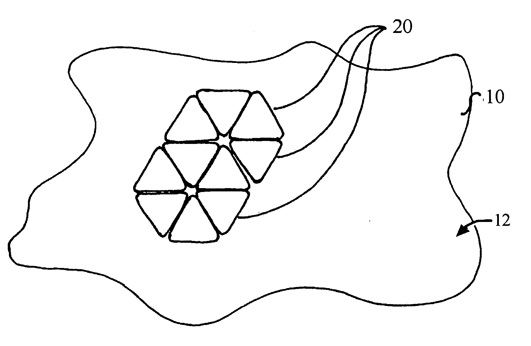
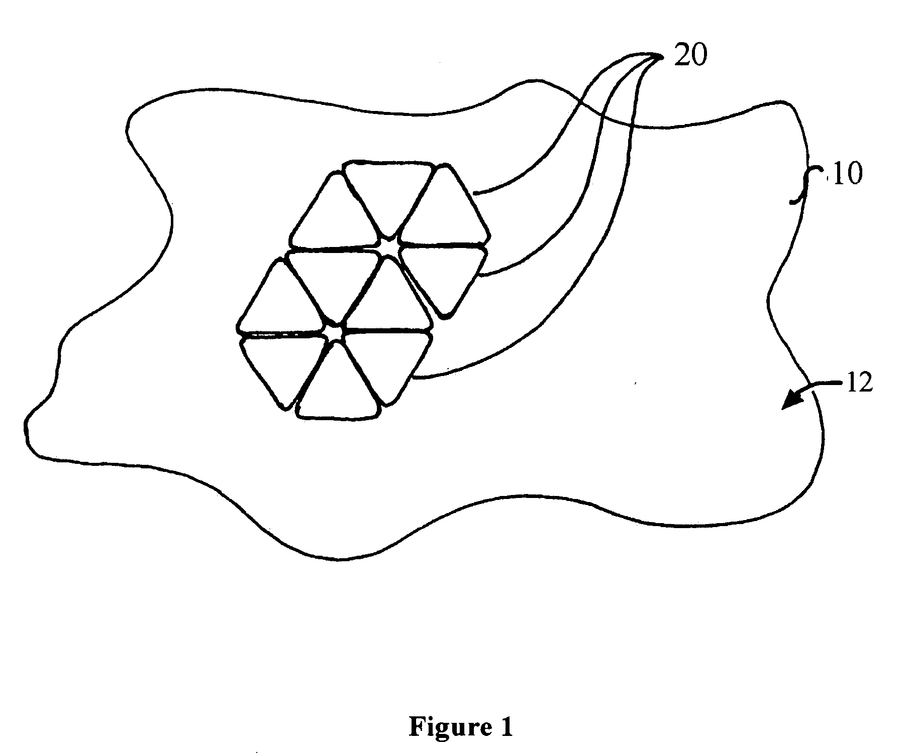
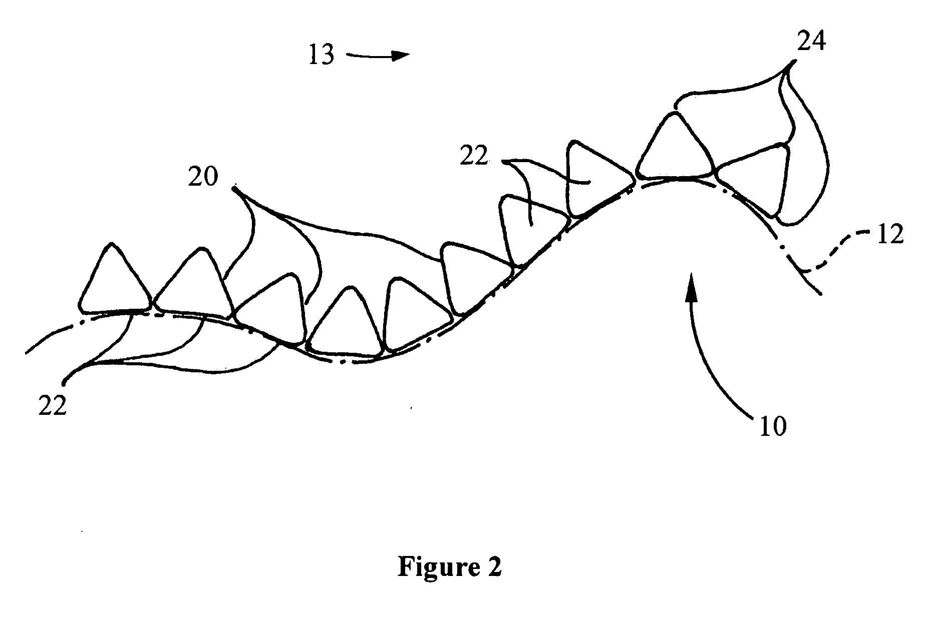
[0024] Embodiments of the present invention provide a system and a method for reducing the rate of evaporation and energy transfer between a body of fluid and an environment. As noted above, the evaporation and energy loss of a fluid can be reduced by decreasing surface area of the fluid that is exposed to the environment above. In one embodiment, a body of fluid having at least a portion of surface covered by buoyant bodies may allow for a reduction of evaporation and energy transfer.

[0025] In general, a buoyant body according to some aspects of the present invention includes a plurality of faces that define its shape and a plurality of edges, where each edge is formed by two intersecting faces. The buoyant body may be designed such that when a sufficient number of like buoyant bodies are placed on a body of fluid, they may aggregate and form a substantially gapless barrier separating the fluid from an environment above.

[0026] The edges of a buoyant body may be rounded or beveled...


PUM


Abstract

A system for reducing an evaporation and energy transfer rate between a body of fluid and an environment is provided. The system comprises a plurality of buoyant bodies, where each of the plurality of buoyant bodies has a shape that is defined by a plurality of faces and edges, and where each edge is formed by two intersecting faces. The bodies are disposed or partially submerged in the fluid so that at least a portion of a first face of a first body contacts at least a portion of a first face of a second body to form a substantially gapless barrier between the surface of the fluid and the environment.

Description

CROSS-REFERENCE TO RELATED APPLICATIONS [0001] This application claims priority, pursuant to 35 U.S.C. § 119(e), of U.S. Provisional Application Ser. No. 60 / 629,367 filed on Nov. 19, 2004.BACKGROUND OF INVENTION [0002] Reducing pollutants (which may result from fluid evaporation) and / or fluid loss generally are major concerns for both industry and the public. These concerns are often of particular concern in the chemical and petroleum industries where substantial sums of money are lost yearly due to the evaporation of volatile substances. Moreover, environmental concerns require stringent regulation of fluid pollutants and toxins contained in standing fluids; thus, evaporation of volatile substances pose both an environmental and a financial burden. [0003] Moreover, these concerns are not limited to bodies of toxic fluids. For example, the evaporation of non-toxic materials is also problematic in regions permanently subjected to arid weather or areas temporarily experiencing unusual...

Claims


Application Information

Patent Timeline
IPC IPC(8): B09C1/00
CPCB65D88/36E04H4/08B33Y80/00
Inventor SMITH, NORMAN LOUIS
Owner SMITH NORMAN LOUIS
Learn More