Suspension control arm assembly for vehicles

a technology for suspension systems and control arms, applied in the direction of suspension arms with flexural properties, vehicle components, etc., can solve the problems of large forging presses, large mass, and high cost of control arms formed of a plurality of stampings, and achieves less mass, less cost, and sufficient ductility.

Inactive Publication Date: 2006-05-25
GENERAL MOTORS COMPANY
View PDF39 Cites 10 Cited by
  • Summary
  • Abstract
  • Description
  • Claims
  • Application Information

AI Technical Summary

Benefits of technology

[0009] One advantage of the present invention is that a new control arm assembly is provided for a suspension system of a vehicle. Another advantage of the present invention is that the control arm assembly incorporates a control arm that is manufactured from a single piece of extruded aluminum to which bushings and / or balljoint(s) are added. Yet another advantage of the present invention is that the control arm assembly incorporates an aluminum control arm that has less mass that a steel control arm. Still another advantage of the present invention is that the control arm assembly has an extruded aluminum control arm that is less expensive than a cast aluminum control arm due to the cost of extrusion dies versus casting molds. A further advantage of the present invention is that the control arm assembly has an aluminum control arm made of aluminum alloys that are extruded and have sufficient ductility to allow for ductile bending / buckling. Yet a further advantage of the present invention is that the control arm assembly includes a one-piece or single piece control arm that reduces piece count and number of components that are required to be fastened together through bolting, riveting, welding, or other fastening mechanisms.
[0010] Other objects, features, and advantages of the present invention will be readily appreciated, as the same becomes better understood, after reading the subsequent description taken in conjunction with the accompanying drawings.

Problems solved by technology

However, castings require molds that are relatively expensive and have to be of a size large enough to prevent ductile bending.
Forgings require large presses that are not efficient in the use of raw materials and are expensive.
Control arms formed of a plurality of stampings are expensive and difficult to manufacture.

Method used


Image

  • Suspension control arm assembly for vehicles
  • Suspension control arm assembly for vehicles
  • Suspension control arm assembly for vehicles

Examples


Embodiment Construction

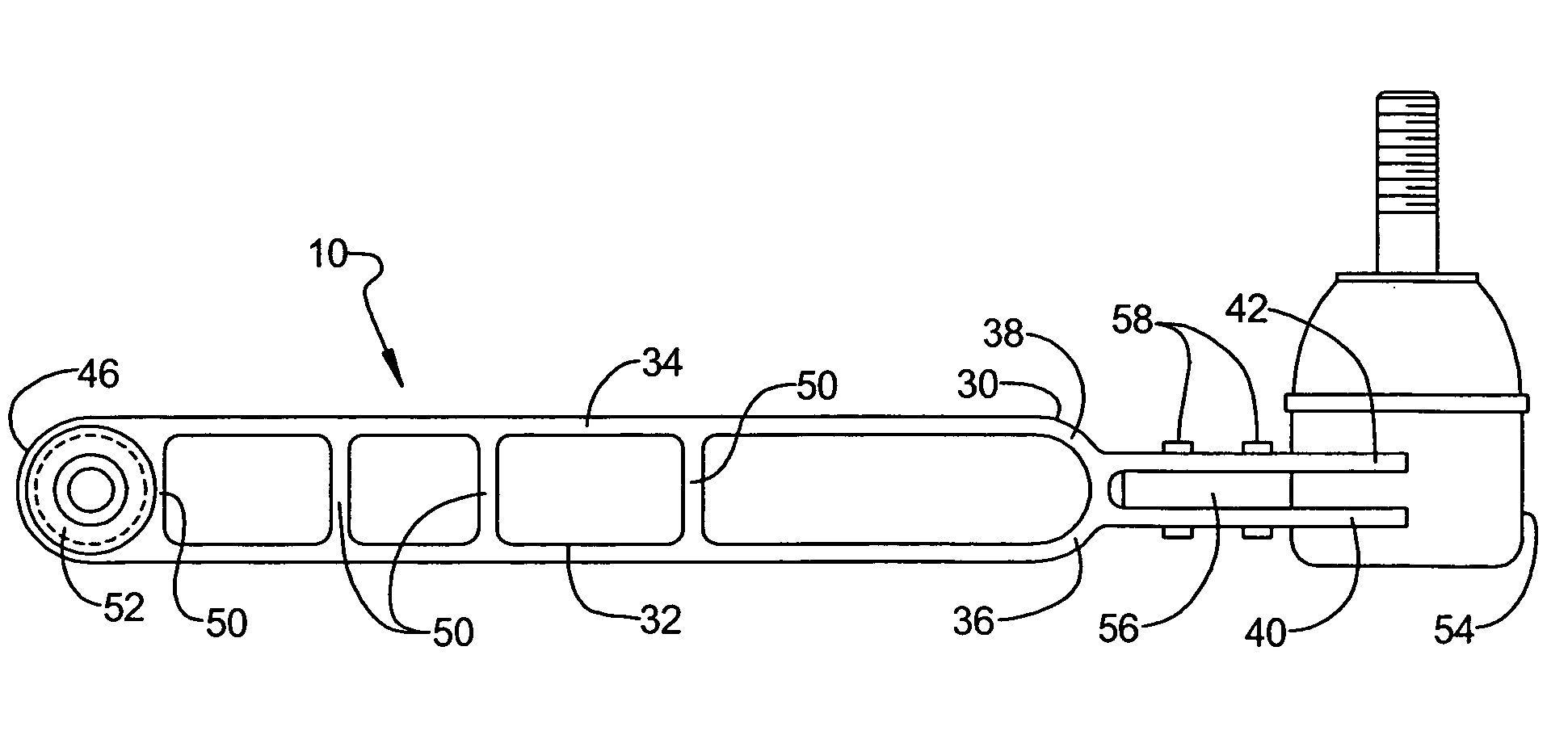
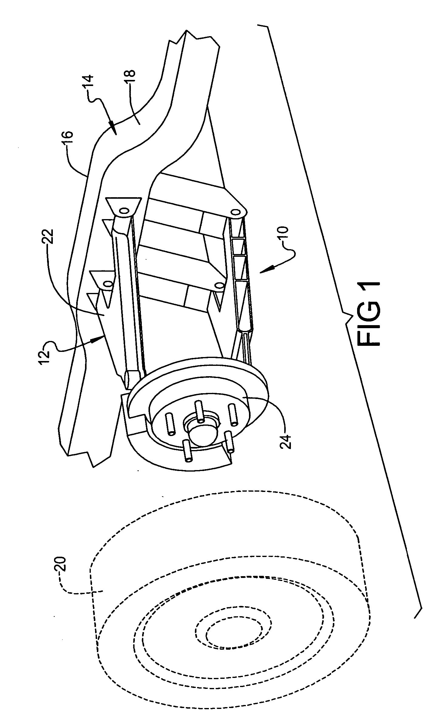
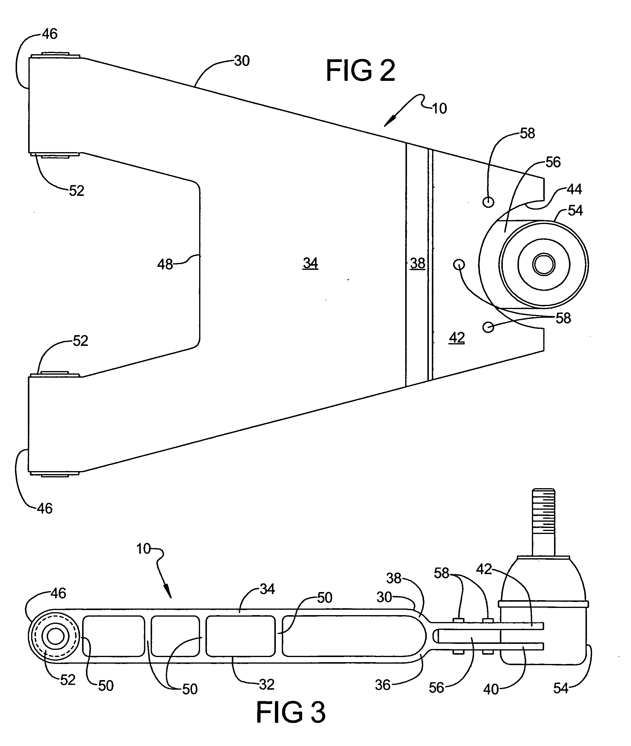
[0016] Referring to the drawings and in particular FIG. 1, one embodiment of a control arm assembly 10, according to the present invention, is shown for a suspension system, generally indicated at 12, of a vehicle, such as a motor vehicle (partially shown), generally indicated at 14. The vehicle 14 includes a frame 16 having at least one, preferably a pair of side rails 18 (only one illustrated) generally parallel to a longitudinal centerline of the frame 16 and a rigid cross member (not shown) between the side rails 18. The vehicle 14 also includes at least one, preferably a plurality of wheels 20 connected to the suspension system 12 to suspend the frame 16 relative to the wheels 20.

[0017] The suspension system 12 includes an upper control, arm assembly 22 and the lower control arm assembly 10 supported on the side rail 18 for vertical pivotal movement and a steering knuckle (not shown) connected to the outboard ends of the control arm assemblies 20,10 for vertical suspension exc...


PUM


Abstract

A control arm assembly for a suspension system of a vehicle includes a one-piece extruded control arm for operative connection to a frame of the vehicle. The control arm assembly also includes at least one of a bushing and/or balljoint connected to the control arm and for connection to structure of the vehicle.

Description

CROSS-REFERENCE TO RELATED APPLICATION(S) [0001] The present application claims the benefit of copending U.S. Provisional Patent Application Ser. No. 60 / 630,586, filed Nov. 23, 2004.TECHNICAL FIELD [0002] The present invention relates generally to suspension systems for vehicles and, more particularly, to a control arm assembly for a suspension system of a vehicle. BACKGROUND OF THE INVENTION [0003] It is known to provide a suspension system for a vehicle. In a vehicle such as an automotive vehicle, the suspension system typically includes a pair of control arms supported on a side rail of a vehicle frame for vertical pivotal movement and a steering knuckle connected to the outboard ends of the control arms for vertical suspension excursions. The suspension system typically includes a spring disposed between the frame and the lower control arm. [0004] One typical control arm is formed by casting or by forging. However, castings require molds that are relatively expensive and have to...

Claims


Application Information

Patent Timeline
Patent Type & Authority Applications(United States)
IPC IPC(8): B60G7/00
CPCB60G3/20B60G7/005B60G2200/144B60G2204/143B60G2206/012B60G2206/014B60G2206/017B60G2206/12B60G2206/8105
Inventor RAY, MICHAEL A.
Owner GENERAL MOTORS COMPANY
Why Eureka
Try Eureka