Cordless power tool

a power tool and cordless technology, applied in the field can solve the problems of high running cost, and achieve the effects of reducing the size and weight of cordless power tools, shortening the charging time, and reducing the running cos

Inactive Publication Date: 2006-05-25
MAX CO LTD
View PDF4 Cites 8 Cited by
  • Summary
  • Abstract
  • Description
  • Claims
  • Application Information

AI Technical Summary

Benefits of technology

[0004] Thus, in order to reduce the size and weight of a cordless power tool, to shorten the charging time, and to reduce

Problems solved by technology

Besides, the conventional secondary battery has a charge/discharge lifetime of approximately several hundred to one thousand cycles, which is generally shorter than

Method used


Image

  • Cordless power tool
  • Cordless power tool
  • Cordless power tool

Examples


Embodiment Construction

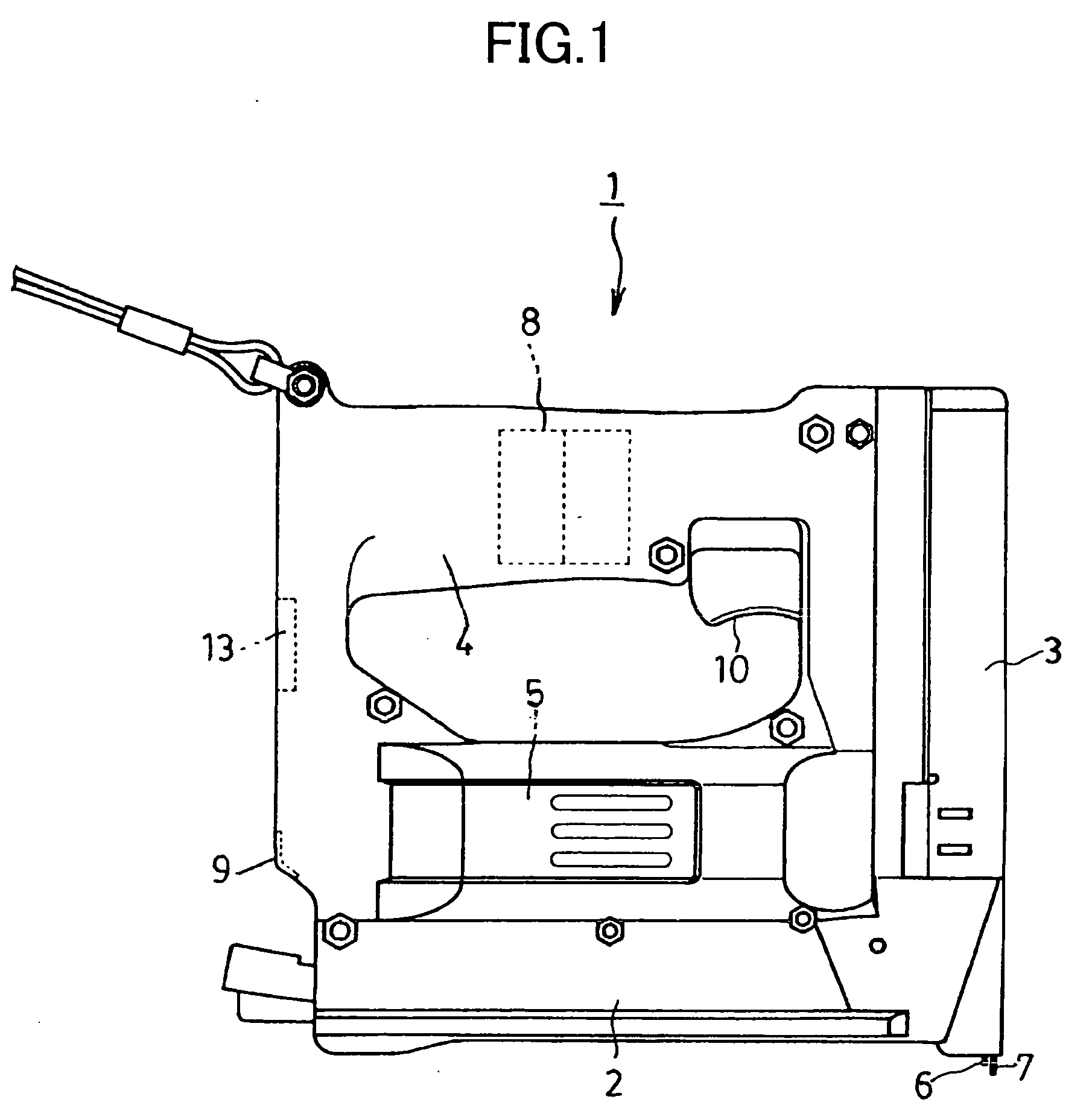
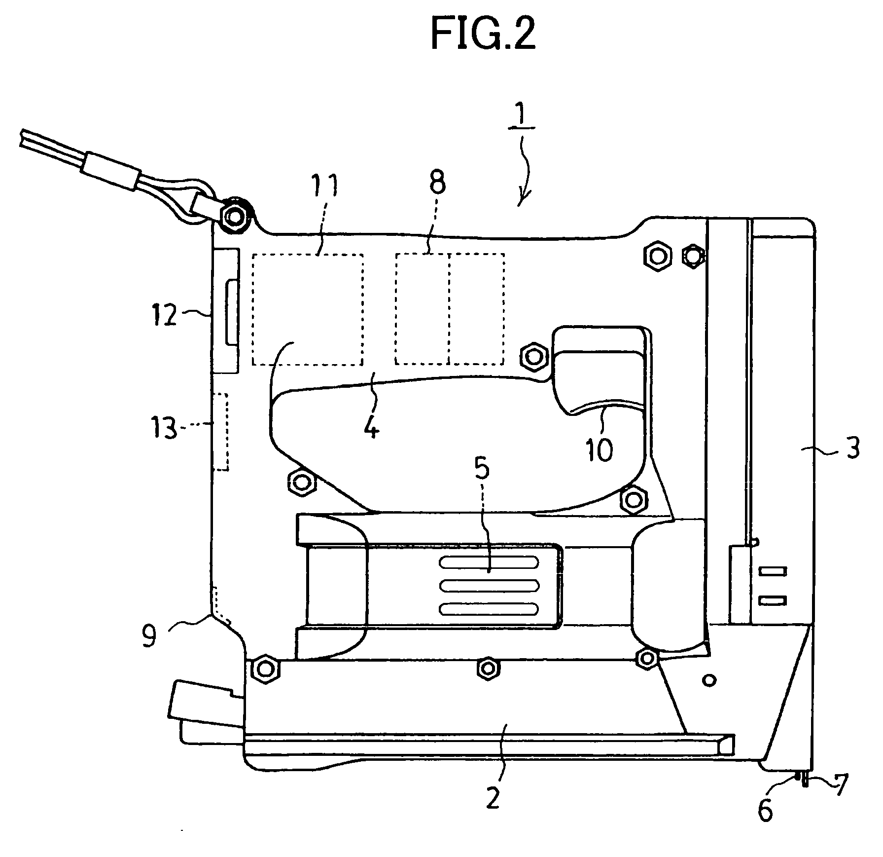
[0013] Hereinafter, an embodiment of the invention will be described in detail with reference to the drawings. FIG. 1 shows a power staple gun 1 as an example of a cordless power tool, in which a lower part of a housing is a staple magazine part 2, a driver mechanism part 3 is vertically disposed at the front part (right in the drawing), and a grip part 4 extends rearward from the upper back of the driver mechanism part 3. A DC motor 5 is disposed on the staple magazine part 2, and drives the driver mechanism part 3 through a reduction gear mechanism and a cam mechanism (not shown).

[0014] The driver mechanism part 3 includes a driver 6 for driving a staple and a contact arm 7 as a safety mechanism, and the contact arm 7 protrudes downward from the lower end of the driver mechanism part 3. Incidentally, in the drawing, although the driver 6 also protrudes downward, in the initial state, the driver 6 is pushed up to an upper standby position by the cam mechanism in the driver mechani...


PUM


Abstract

A cordless power tool such as a power staple gun 1 includes a power supply circuit of an electric double layer capacitor 8 and a lithium-ion battery 11. In a standby state, the lithium-ion battery charges the electric double layer capacitor, and at a switch on time, the electric double layer capacitor supplies large current to the motor 5. By combining the lithium-ion battery with high energy density and the electric double layer capacitor capable of discharging large current, it is possible to greatly reduce the size and weight as compared with a case where a nickel-cadmium battery or a nickel-hydrogen battery is used. Besides, since the electric double layer capacitor has a very long lifetime, the running cost can also be reduced.

Description

TECHNICAL FIELD [0001] The present invention relates to a cordless power tool, and particularly to a cordless power tool in which the size and weight of a power supply part is reduced. BACKGROUND ART [0002] Conventionally, a cordless power tool generally uses a battery pack of a nickel-cadmium battery, a nickel-hydrogen battery or the like as a drive power supply, and when the secondary battery mounted on a cordless power tool main body is exhausted, the cordless power tool is connected to a dedicated recharger, or the battery pack removed from the cordless power tool is charged and is repeatedly used (for example, see JP-UM-A-06-000679, JP-A-10-029172). [0003] In the conventional cordless power tool, since the weight of the secondary battery relative to the main body is heavy, and charging takes time, it is desired to reduce the size and weight of the power supply and to shorten the charging time. Besides, the conventional secondary battery has a charge / discharge lifetime of approx...

Claims


Application Information

Patent Timeline
IPC IPC(8): H02J7/00B25F5/00B25C5/15B25H3/00H02J7/34
CPCB25C5/15B25H3/006H02J7/345
Inventor OOKUBO, SHINICHIMATSUOKA, ATSUSHIISHII, SYUICHI
Owner MAX CO LTD
Why Eureka
Try Eureka