Device for reflecting electromagnetic radiation

a technology of electromagnetic radiation and reflector, which is applied in the field of reflectors, can solve the problems of high cost of each packaged device, inability to provide the desired impedance performance characteristics of low-cost transistors, and prohibitively high cost of reflectarrays with such devices. achieve the effect of optimal phase-amplitude performan

Active Publication Date: 2006-05-25
AGILENT TECH INC
View PDF11 Cites 36 Cited by
  • Summary
  • Abstract
  • Description
  • Claims
  • Application Information

AI Technical Summary

Benefits of technology

[0004] A reflectarray utilizes switching devices with non-ideal impedance characteristics to vary the impedance of reflecting elements. The antennas of the reflecting elements are configured as a function of the impedance of the non-ideal switching devices to provide optimal phase-amplitude performance. In particular, the antennas are configured such that the impedance of each antenna is proportional to the square root of the impedance of the non-ideal switching devices when in an on state and when in an off state. Configuring the antennas as a function of the impedance of the non-ideal switching devices enables a reflectarray to achieve switching between 0 and 180 degree phase-amplitude states while utilizing low-cost switching devices, such as surface mount field effect transistors, which exhibit non-ideal impedance characteristics over the operating frequency range of the reflectarray.

Problems solved by technology

However, these low cost transistors do not necessarily provide the desired impedance performance characteristics at relatively high radio frequency ranges (e.g., greater than 20 GHz).
More expensively packaged transistors as well as more exotic devices, such as ferroelectric capacitors and ferrite switches, are readily able to provide the desired impedance characteristics at the higher frequency ranges, but the number of transistors, capacitors, or switches required for many reflectarray applications combined with the high cost of each packaged device makes reflectarrays with such devices prohibitively expensive.

Method used


Image

  • Device for reflecting electromagnetic radiation
  • Device for reflecting electromagnetic radiation
  • Device for reflecting electromagnetic radiation

Examples


Embodiment Construction

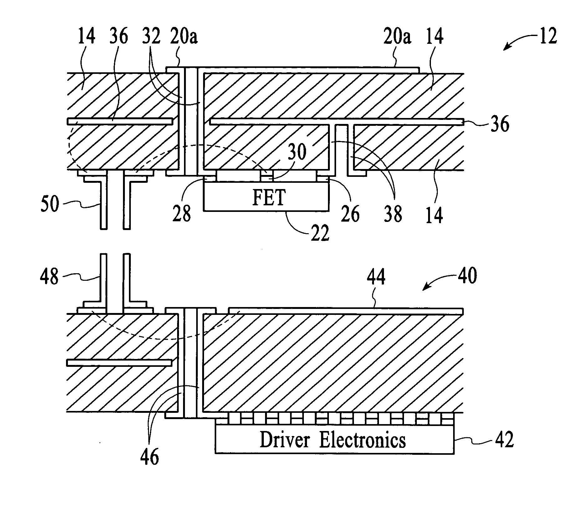
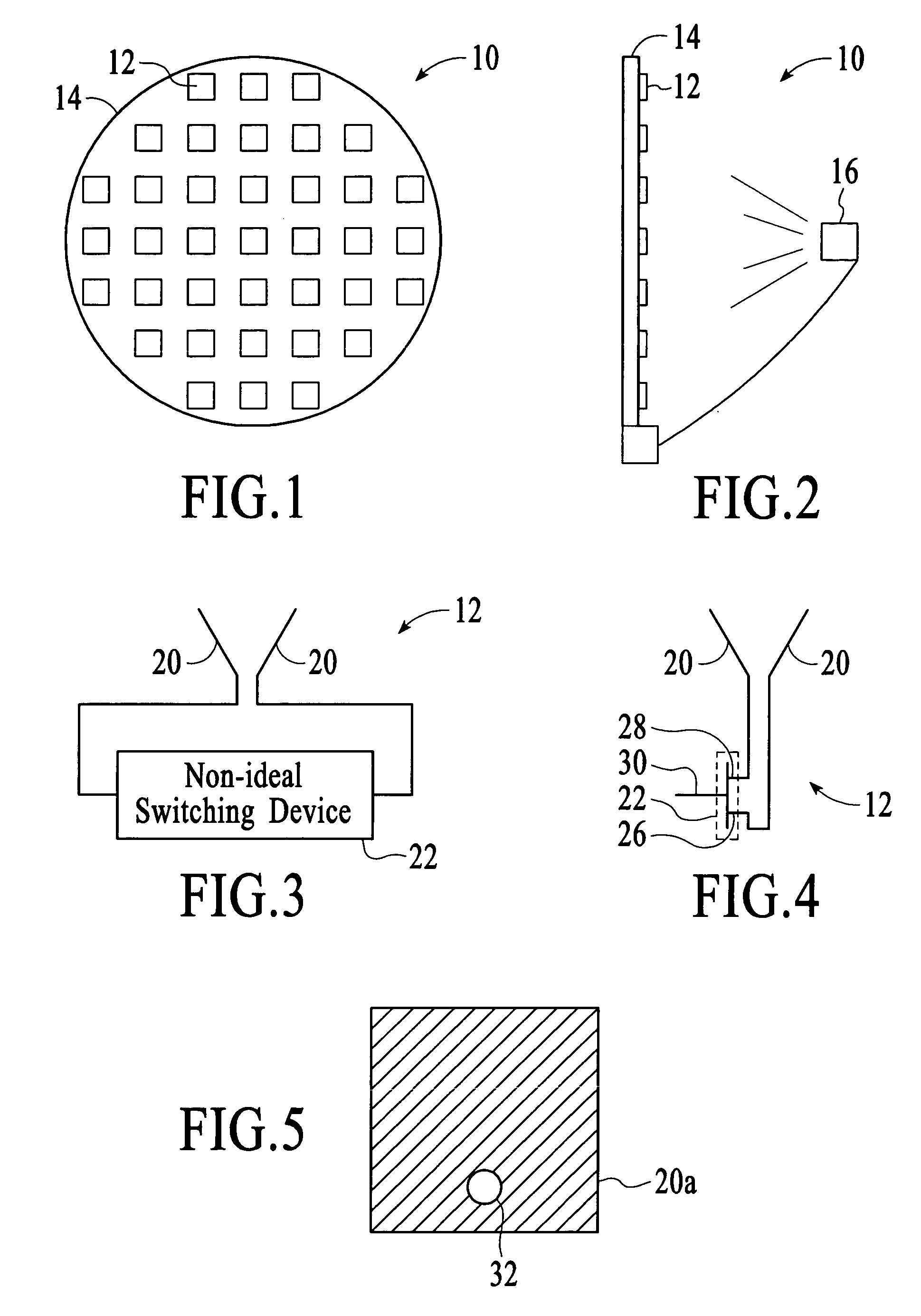
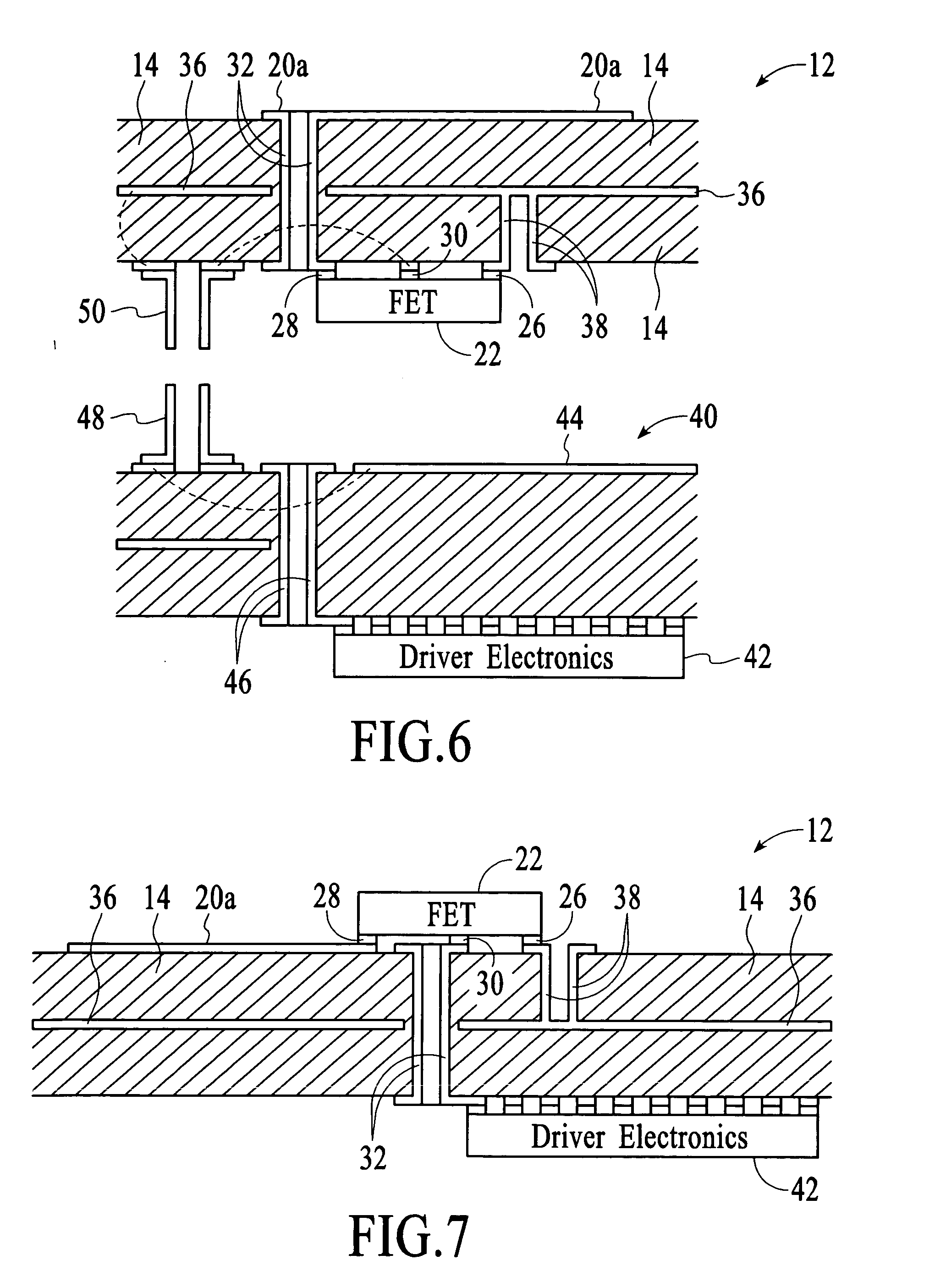
[0014] A reflectarray utilizes switching devices with non-ideal impedance characteristics to vary the impedance of reflecting elements. The antennas of the reflecting elements are configured as a function of the impedance of the non-ideal switching devices to provide optimal phase-amplitude performance. In particular, the antennas are configured such that the impedance of each antenna is proportional to the square root of the impedance of the non-ideal switching devices when in an on state and when in an off state.

[0015] Reflectarrays are passive systems that reflect externally provided electromagnetic radiation. FIG. 1 depicts an example of a reflectarray 10 for microwave and millimeter-wave applications. The reflectarray includes distinct reflecting elements 12 that reflect electromagnetic radiation with varying phase depending on their impedance state. Ideally, the reflecting elements reflect electromagnetic radiation with a phase shift of 180 degrees when their impedance is hig...


PUM


Abstract

A reflectarray utilizes switching devices with non-ideal impedance characteristics to vary the impedance of reflecting elements. The antennas of the reflecting elements are configured as a function of the impedance of the non-ideal switching devices to provide optimal phase-amplitude performance. In particular, the antennas are configured such that the impedance of each antenna is proportional to the square root of the impedance of the non-ideal switching devices when in an on state and when in an off state.

Description

BACKGROUND OF THE INVENTION [0001] Microwave and millimeter-wave reflectarrays are antenna arrays in which each antenna is connected to a variable impedance device. If the variable impedance device is a resistive device, ideally it is biased at either short-circuit or open-circuit states or at least at states of very low or very high resistance compared to the antenna impedance. In this way, the antenna and variable impedance device combination acts as a variable-phase reflecting element. With appropriate control signals applied to the variable impedance devices, the reflectarray can be used as an adjustable mirror with the capability of focusing, steering, or splitting a beam of electromagnetic radiation. [0002] Diodes have typically been used as the variable impedance devices in reflectarrays although transistors have also been used. Many low cost transistors are able to provide the desired impedance characteristics at relatively low radio frequency ranges (e.g., less than 10 GHz)...

Claims


Application Information

Patent Timeline
Patent Type & Authority Applications(United States)
IPC IPC(8): H01Q1/38
CPCH01Q3/46H01Q15/148H01Q19/10H01Q21/0018H01Q23/00H05K1/16H05K1/181H05K3/429H05K2201/0949H05K2201/10166
Inventor LEE, GREGORY STEVENTABER, ROBERT C.KOFOL, JOHN STEPHEN
Owner AGILENT TECH INC
Why Eureka
Try Eureka