Structure of turbine blower

a technology of turbine blower and structure, which is applied in the direction of marine propulsion, vessel construction, other chemical processes, etc., can solve the problems of decreasing power consumption of turbines instead of increasing, and achieve the effect of reducing the loading of motors, reducing the load of air compressors, and increasing the expelling quantity

Inactive Publication Date: 2006-05-25
CHEN GING CHUNG
View PDF3 Cites 9 Cited by
  • Summary
  • Abstract
  • Description
  • Claims
  • Application Information

AI Technical Summary

Benefits of technology

[0007] The primary object of the invention is to provide an improved structure for turbine blowers. With this design of impellers, we can control and maintain the existence of the positive and the negative air pressure produced by the blower, and thus lower the loading the motor.
[0009] Based on the structure described above, the turbine of the improved structure, which is composed of a round bottom board and the impellers, is installed inside an air hood. The air hood comprises an air inlet and an air outlet. The air inlet is installed above the center of the turbine (the pivot center), and the air outlet is installed on the outer rim of the turbine corresponding to the air inlet. Since the height of the rear of the impellers is higher, when the turbine rotates at high speed, the active surface, that the rear of the impeller formed by hitting the air, becomes larger and causes the increase of the pushing force against the air formed between the corresponding low point of the middle section and the rear of the impeller. The positive pressure in the expelling area (expelling quantity) in the rear of the impeller increases in order to have better air compression ratio (and larger expelling quantity). When the air inlet or the air outlet of the turbine is partially obstructed, the positive air pressure in the rear of impellers is guided to the rotation cylinder space in the front of the impellers to let the negative and the positive air pressure counterbalance each other. Till then, the power consumption of the turbine decreases instead of increasing, therefore, it can have the effect of decreasing the loading of motor.

Problems solved by technology

Till then, the power consumption of the turbine decreases instead of increasing, therefore, it can have the effect of decreasing the loading of motor.

Method used


Image

  • Structure of turbine blower
  • Structure of turbine blower
  • Structure of turbine blower

Examples


Embodiment Construction

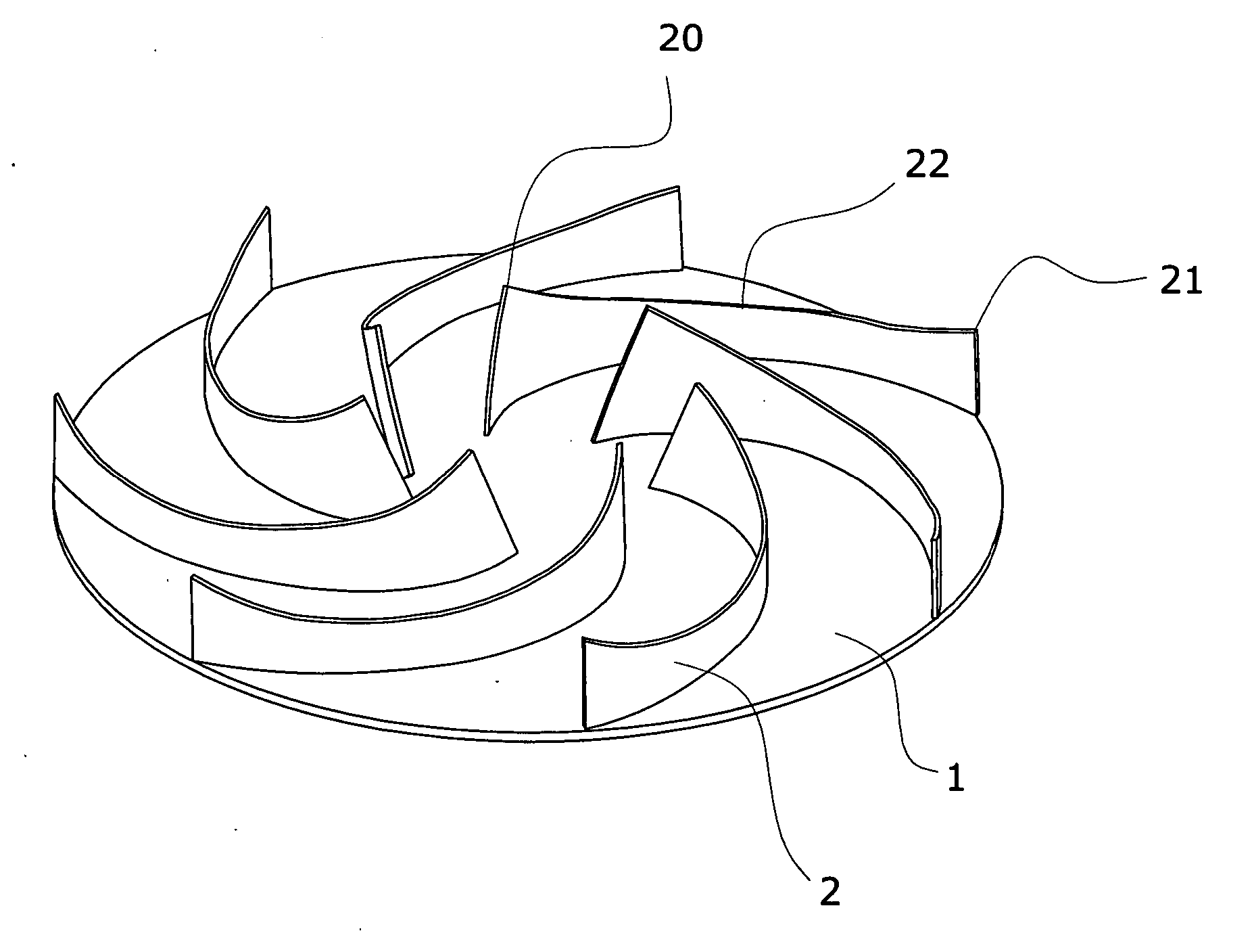
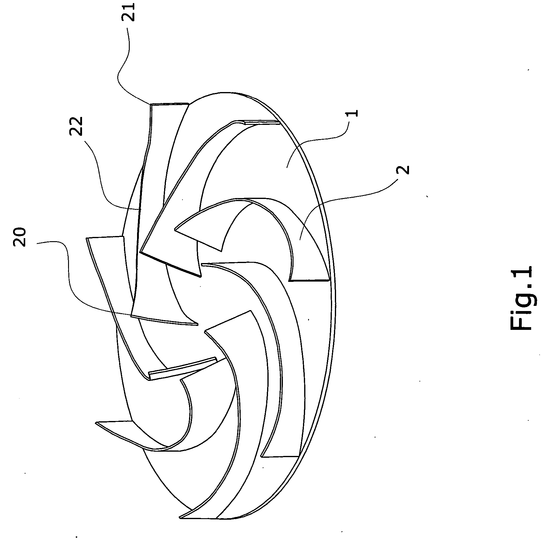
[0016] Referring to FIG. 1 to FIG. 3, the improved structure for turbine blower of the present invention has several impellers 2 installed on the surface of the round bottom board 1. The impellers 2 stretch out from near the center of the bottom board 1 in a radial curve shape to the outer brim of the bottom board 1. The round bottom board 1 and the impellers 2 are installed inside an air hood 3. The air hood 3 further comprises an air inlet 31 and an air outlet 32. The air inlet 31 is installed above the center of the turbine and the air outlet 32 is installed on the outer rim of the turbine corresponding to the air inlet 31. The function of each component is described as following:

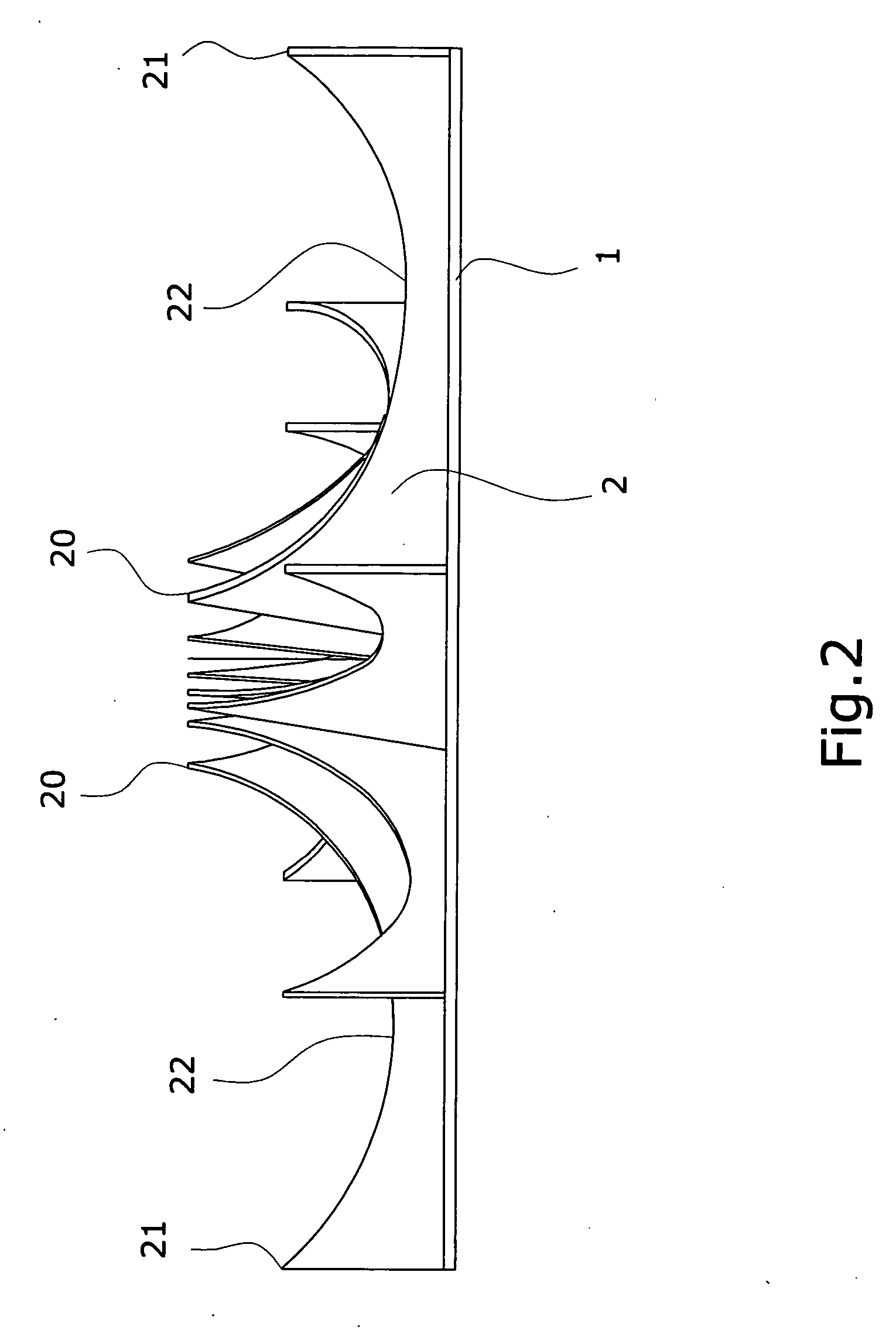
[0017] The height of the impeller 2 is the curve that starts from the front 20 of the center of the impeller and lowers down gradually to a corresponding low point 22, and then elevates gradually from the corresponding low point 22 to the rear of the impeller 21. The top rim between the front 20 and the...


PUM


Abstract

“An improved structure of turbine blower”, is mainly about installing several impellers in the form of a radial arrangement on a round bottom board. The characteristic of the design is that, the height of the impeller starts from the front of the impeller, near the center of the bottom board, lowers down to the corresponding low point in the middle section and elevates gradually to the front of the impeller. The top brim between the front and the rear of the impeller is in a curve shape. According to the above structure, when the air inlet or air outlet is obstructed, the power consumption will decrease automatically, so that the loading of the motor will be reduced.

Description

BACKGROUND OF THE INVENTION [0001] I. Field of the Invention [0002] This invention relates generally to an improved structure of turbine blowers, especially the kind of turbine structure that decreases the power consumption automatically when the air inlet or air outlet is obstructed, and could reduce the loading of the motor. [0003] II. Description of the Prior Art [0004] Heretofore, it is known that the structure of turbine blowers, as shown in FIG. 5, is to have several impellers b installed around the center of a round bottom board a. The impellers b stretch out from the proximity of the center of the round bottom board a to the outer brim of the round bottom board a in the form of a radial curve. The front b1 of the impeller b is located near the center of the round bottom board a. The height of the impeller b is the curve that starts from the front b1 to the lowest point of the rear b2 which gradually stretches out toward the outside horizontally. The turbine which is composed...

Claims


Application Information

Patent Timeline
Patent Type & Authority Applications(United States)
IPC IPC(8): B64C11/00F04D29/24
CPCF04D29/281Y10S416/02
Inventor CHEN, GING-CHUNG
Owner CHEN GING CHUNG
Why Eureka
Try Eureka