
Radial piston fuel supply pump

a technology of radial piston and fuel supply pump, which is applied in the direction of piston pump, positive displacement liquid engine, machine/engine, etc., can solve the problems of affecting life expectancy and other problems, and achieve the effect of avoiding sharp angles, avoiding intense stress, and balancing torque loading on the foot at either extreme of the contact of the actuating member

Active Publication Date: 2006-05-25
STANADYNE OPERATING CO LLC (
View PDF5 Cites 10 Cited by
  • Summary
  • Abstract
  • Description
  • Claims
  • Application Information

AI Technical Summary

Benefits of technology

"The invention is a hydraulic head with a unique design that includes multiple pistons and associated pumping chambers. The pistons are actuated by an eccentric driving ring and a rolling actuation ring, which allows for intermittent actuation. The actuation force is sequentially transferred from the driving ring to the pistons through a rolling actuation ring, which compensates for any misalignment of the pistons. The pump has a flared shape for improved performance and reduced stress concentration. The pistons are in the form of a C-band spring that is retained within a guide channel of the cavity wall, which allows for reciprocation of the pistons. The invention also includes a beveled capture hole and contoured foot for improved performance and reduced wear. The pump can have two or three sets of opposed pumping chambers for even higher capacity."

Problems solved by technology

The rigidity of the yoke must be adequate to minimize deflection (even at maximum vacuum at zero output conditions), as any separation and subsequent impact at the start of pumping would have a detrimental effect on life expectancy.

Method used


Image

  • Radial piston fuel supply pump
  • Radial piston fuel supply pump
  • Radial piston fuel supply pump

Examples


Embodiment Construction

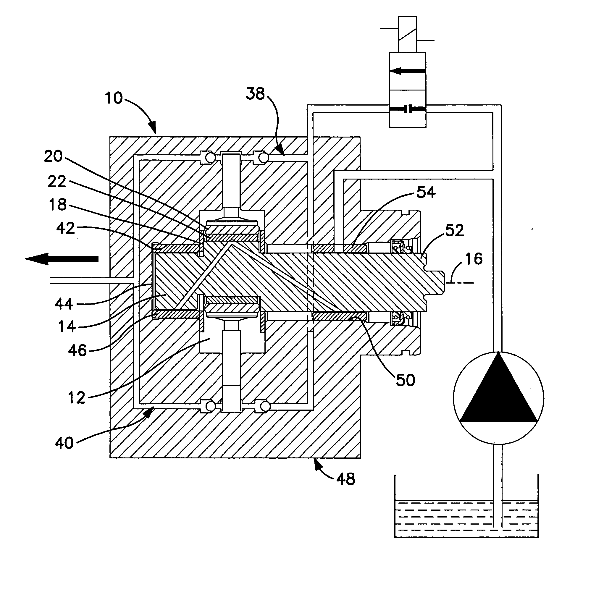
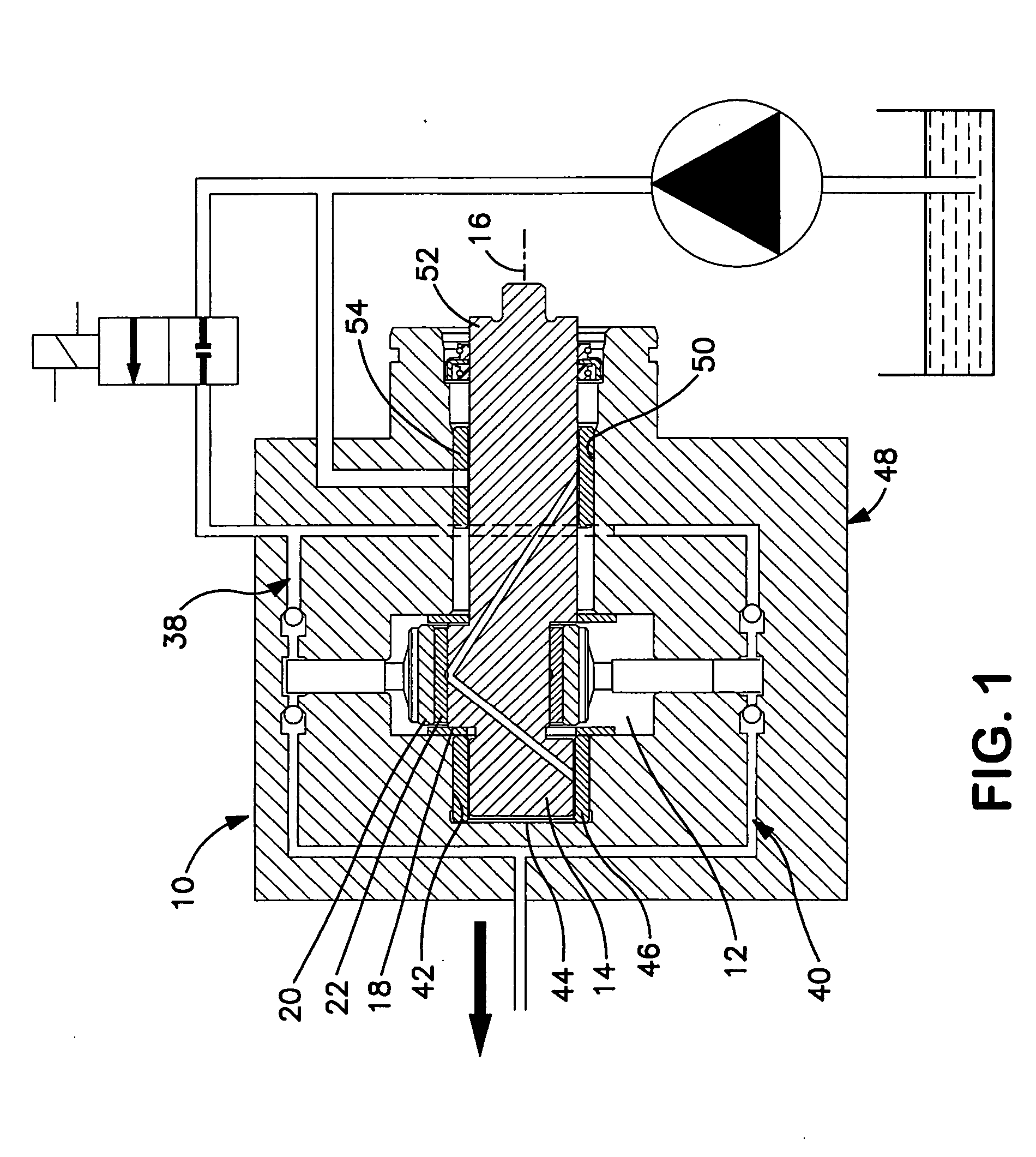
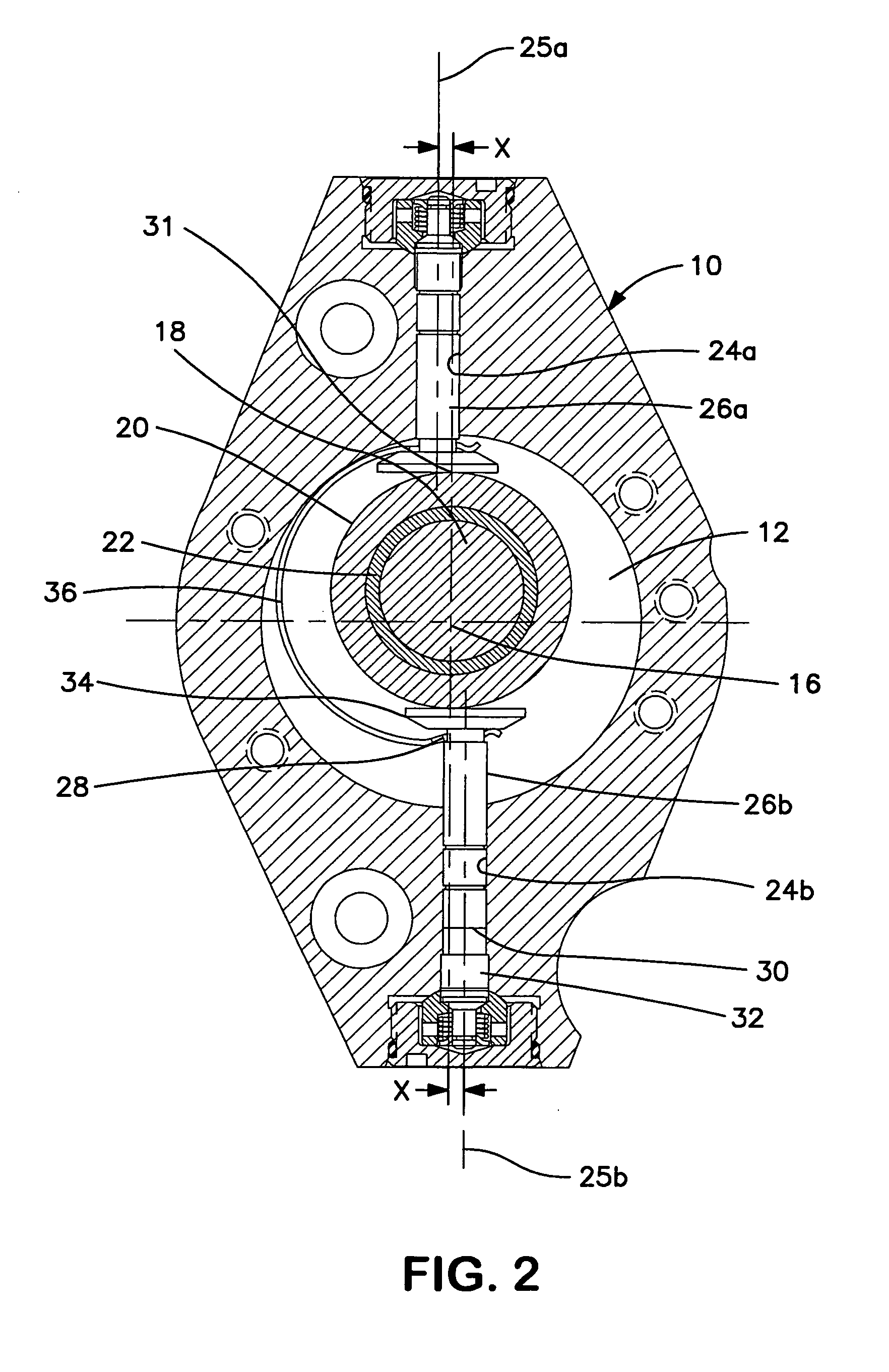
[0033]FIGS. 1 and 2 show a high pressure radial piston fuel pump comprising an hydraulic head 10 defining a central cavity 12 for receiving a rotatable drive shaft 14 longitudinally disposed along a drive axis 16 passing through the cavity. A cylindrical drive member 18 is rigidly carried by and offset from the drive shaft for eccentric rotation in the cavity about the drive axis as the drive shaft rotates. A substantially cylindrical piston actuation ring 20 is annularly mounted around the drive member. Bearing means 22, such as a needle bearing, is interposed between the drive member and the actuation ring, whereby the actuating ring is supported for free rotation about the drive member.

[0034] Two piston bores 24a, 24b extend in the head to the cavity 12, each piston bore having a centerline 25a, 25b that intersects the actuation ring but is offset (x) from the drive axis 16 as viewed along the drive axis (i.e., in section perpendicular to the drive axis). A piston 26a, 26b is si...


PUM


Abstract

An hydraulic head features two, three, or four individual radial pumping pistons and associated pumping chambers, annularly spaced around a cavity in the head where an eccentric drive member with associated outer rolling actuation ring are situated. The piston shoe or foot smoothly enlarges from the piston stem, thereby avoiding the concentration of stress at the interface. Another improvement is in the capture of the piston foot through beveled holes at the ends of a C-band spring such that the bevel substantially conforms to the contour of the foot and thereby reduces stresses and wear. Yet another improvement is that the C-band spring is retained within a guide channel of the cavity wall thereby permitting apparent reciprocating displacement of the spring in parallel with the reciprocation of the pistons, while avoiding axial movement or tilting within the cavity.

Description

RELATED APPLICATION [0001] The application is a continuation-in-part of U.S. application Ser. No. 10 / 857,313 filed May 28, 2003, for “Radial Piston Pump with Eccentrically Driven Rolling Actuation Ring”.BACKGROUND OF THE INVENTION [0002] The present invention relates to diesel fuel pumps, and more particularly, to radial piston pumps for supplying high-pressure diesel fuel to common rail fuel injection systems. [0003] Diesel common rail systems have now become the state of the art in the diesel engine industry and furthermore, they are currently entering into their second and sometimes even third generation. Attention is presently focused on realizing further improvements in fuel economy and complying with more restrictive emission laws. In pursuit of these goals, engine manufacturers are more willing to select the most effective component for each part of the overall fuel injection system, from a variety of suppliers, rather than continuing to rely on only a single system integrato...

Claims


Application Information

Patent Timeline
Patent Type & Authority Applications(United States)
IPC IPC(8): F04B41/06F04B23/04F02M39/02F02M59/06F02M59/10F04B1/053F04B7/06
CPCF02M59/102F04B1/053F04B1/0531F04B1/0404F04B1/0421
Inventor DJORDJEVIC, ILIJABALTRUCKI, JUSTIN D.PARADIS, CRAIG A.
Owner STANADYNE OPERATING CO LLC (
Learn More