

Exhaust gas purifying apparatus
- Summary
- Abstract
- Description
- Claims
- Application Information
AI Technical Summary
Benefits of technology
Problems solved by technology
Method used
Image

Examples
Embodiment Construction
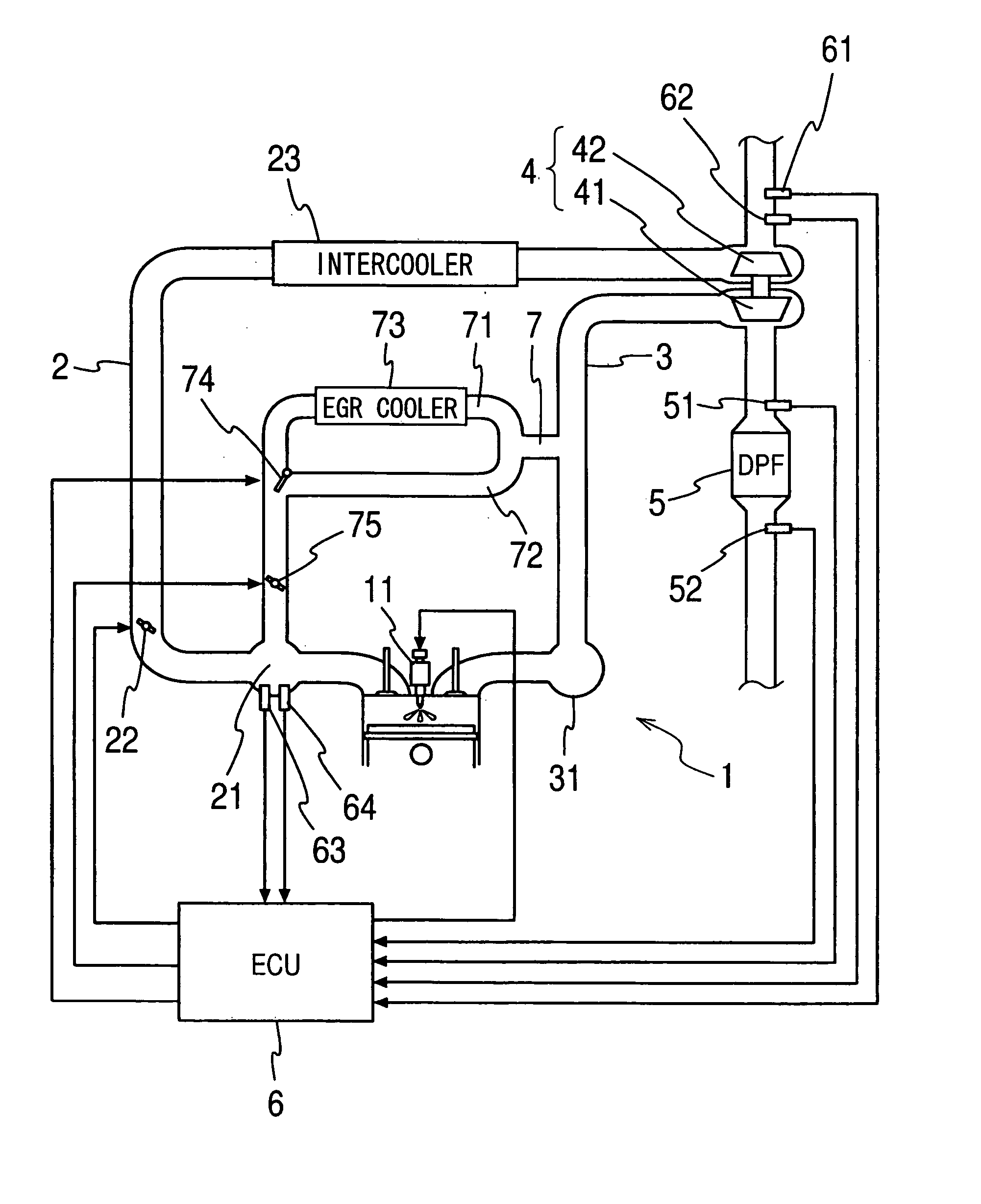
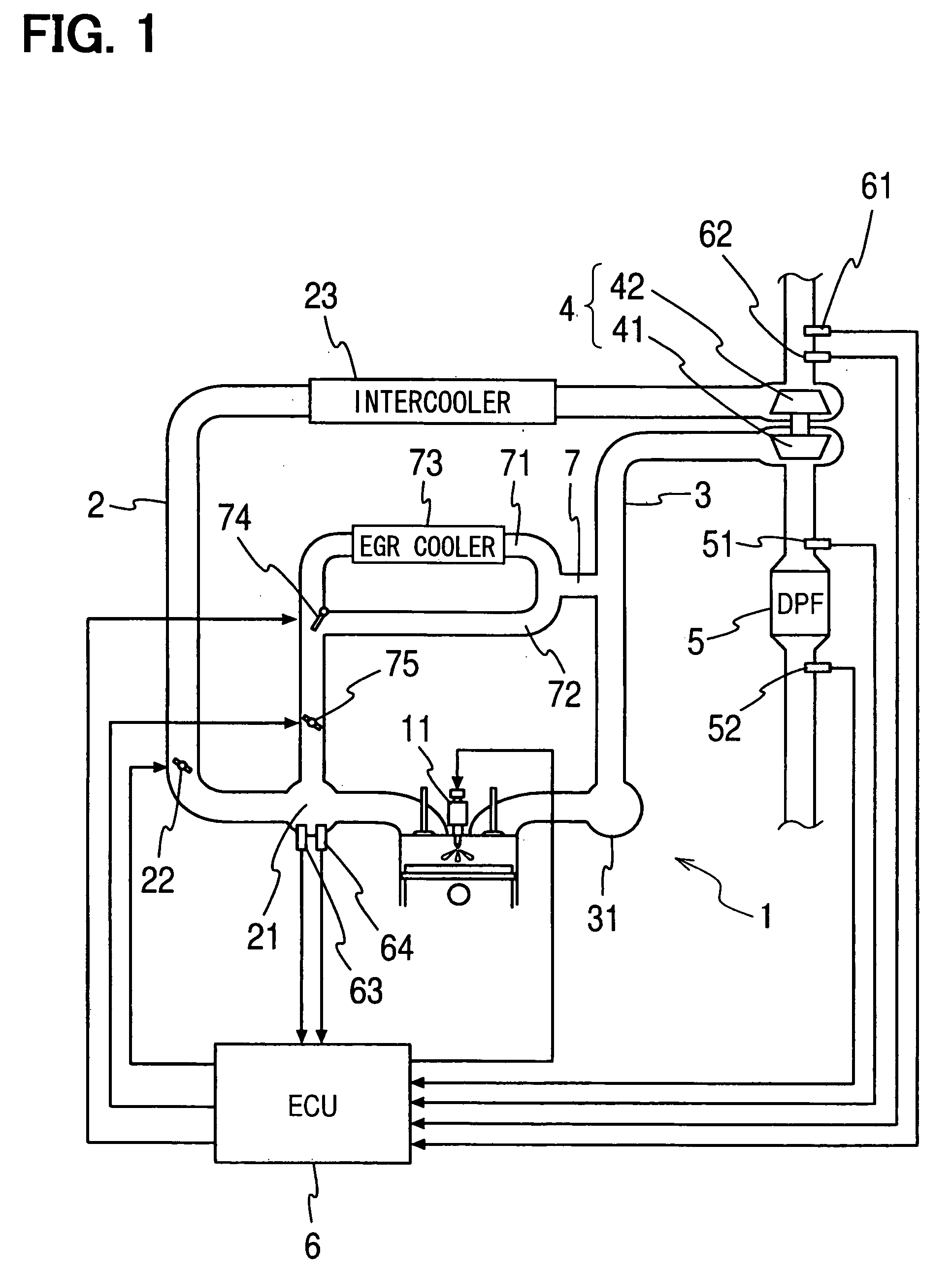
[0027] An embodiment of the present invention will be described with reference to the accompanying drawings. FIG. 1 shows an entire structure of an exhaust gas purifying apparatus for an internal combustion engine, more particularly a diesel engine 1. Combustion chambers of cylinders (only one cylinder depicted in FIG. 1) are connected to an intake air passage 2 and an exhaust gas passage 3 through an intake manifold 21 and an exhaust manifold 31, respectively. An injector 11, which is connected to a fuel supply arrangement (not shown), is provided in each combustion chamber and is driven by an ECU 6 at predetermined timing to inject high pressure fuel into the combustion chamber.
[0028] A centrifugal supercharger 4 is provided to the engine 1. A turbine 41 of the centrifugal supercharger 4 is arranged in the exhaust gas passage 3, and a compressor 42 of the centrifugal supercharger 4 is arranged in the intake air passage 2. The turbine 41 and the compressor 42 are connected to each...
PUM
 Abstract
Description
Claims
Application Information