Method and system to increase dynamic range of time-of-flight (TOF) and/or imaging sensors

Inactive Publication Date: 2006-06-01
MICROSOFT TECH LICENSING LLC
View PDF12 Cites 36 Cited by
  • Summary
  • Abstract
  • Description
  • Claims
  • Application Information

AI Technical Summary

Benefits of technology

[0044] Motion between acquired frames of images can be estimated using multiple exposures to reduced motion artifacts. Once imag

Problems solved by technology

Other prior art systems do not provide an active light source 30 and instead rely upon and indeed require ambient light reflected by the object of interest.
For example, if a CCD range finder system were used in a digital zoom lens application, even though most of the relevant data would be provided by a few of the CCDs in the array, it would nonetheless be necessary to readout the entire array to gain access to the relevant data, a time consuming process.
Unfortunately, as described above, reflected luminosity data does not provide a truly accurate rendering of distance because the reflectivity of the object is unknown.
Further, in very brightly or very dimly illuminated scenes, system 10 may either saturate due t

Method used


Image

  • Method and system to increase dynamic range of time-of-flight (TOF) and/or imaging sensors
  • Method and system to increase dynamic range of time-of-flight (TOF) and/or imaging sensors
  • Method and system to increase dynamic range of time-of-flight (TOF) and/or imaging sensors

Examples


Embodiment Construction

[0065] Reference will now be made in detail to the preferred embodiments of the invention, examples of which are illustrated in the accompanying drawings. While the invention will be described in conjunction with the preferred embodiments, it will be understood that they are not intended to limit the invention to those embodiments. On the contrary, the invention is intended to cover alternatives, modifications and equivalents, which may be included within the spirit and scope of the invention as defined by the appended claims.

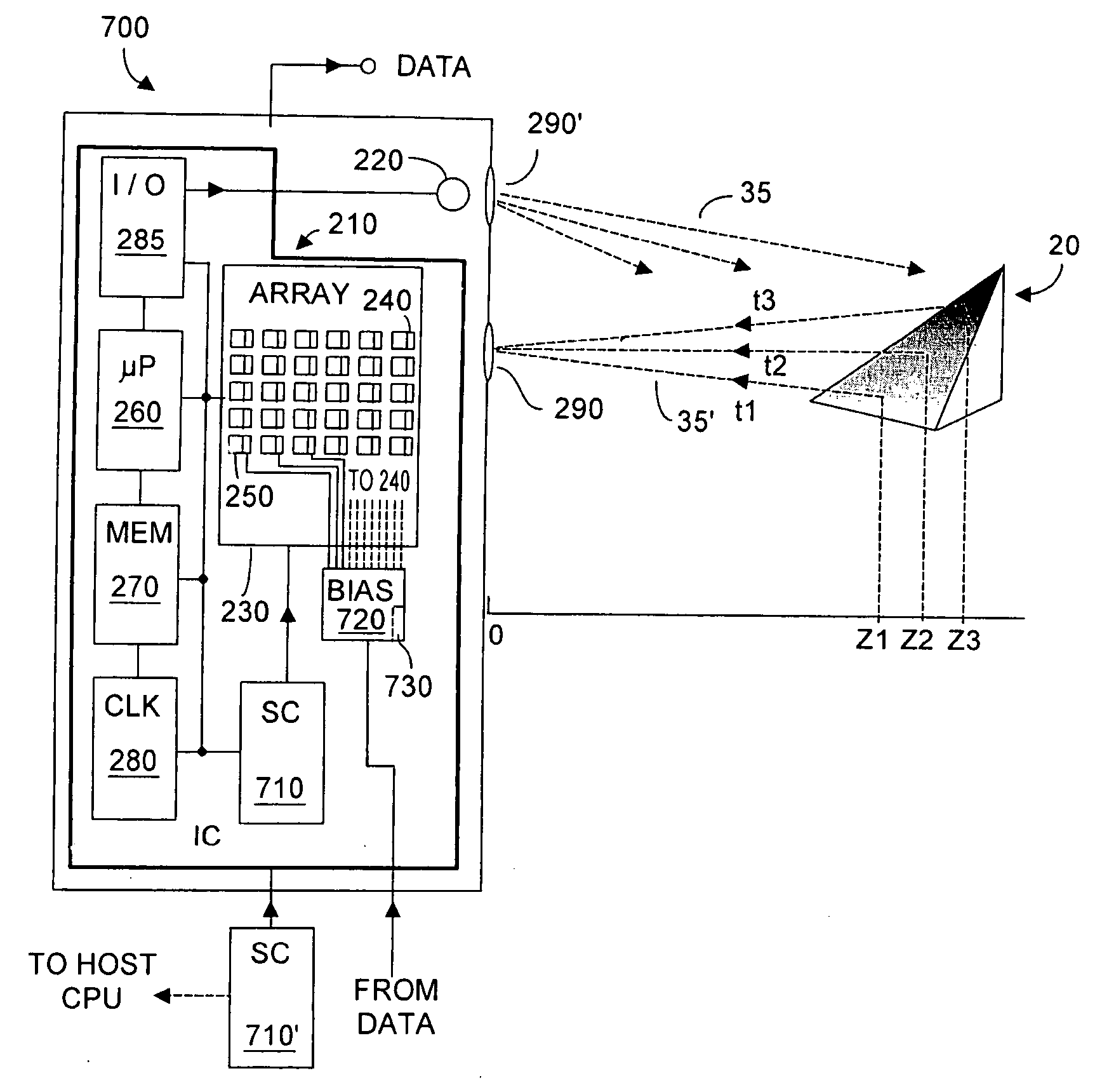
[0066]FIG. 3A is a block diagram of an imaging / range finding TOF system 700, according to the present invention. Unless noted otherwise, elements in FIG. 3A that are identified with reference numerals described with respect to FIG. 2A may be regarded as being the same elements. Within array 240, photodetectors 240 respond to incoming optical energy35′ within a dynamic range (DR). As noted, DR=IntensitymaxIntensityminEq. ⁢(9)

where Intensitymax and Intensitymi...


PUM


Abstract

Dynamic range of photodetector sensors useable in a TOF system is enhanced by capturing images of an object using multiple exposure time settings. Longer exposure settings more appropriately capture non-reflective and/or distant objects, while shorter exposure settings more appropriately capture reflective and/or closer objects. During parallel mode operation, detection signal readouts are taken from each photodetector at different time intervals within an overall exposure time. In sequential mode operation, detection signal readouts are taken and stored for each photodetector at the end of a first exposure time interval and the photodetectors are reset. After a second, different exposure time interval readouts are taken and stored, and the photodetectors reset, etc. In these modes one of the time exposure intervals will be relatively optimum for enhanced dynamic range operation. Once images with multiple exposure settings are obtained, best effort brightness and range images can be obtained, and motion artifacts can be reduced.

Description

CROSS-REFERENCES TO RELATED APPLICATIONS [0001] This application claims priority to U.S. Provisional Patent Application No. 60 / 544,653 filed 12 Feb. 2004, entitled A METHOD FOR INCREASING THE DYNAMIC RANGE OF TIME OF FLIGHT SENSORS, the entire contents of which is incorporated herein by this reference.BACKGROUND OF THE INVENTION [0002] 1. Field of the Invention [0003] The present invention relates generally to solid state sensors useable in time-of-flight (TOF) and / or imaging applications, and more specifically to systems and methods to enhance dynamic range for such sensors, including improving detection from weak signals returned by distant target objects. [0004] 2. Description of Related Art [0005] Solid state sensors used in time-of-flight (TOF) applications are known in the art. Exemplary such TOF sensors are described in U.S. Pat. No. 6,323,942 to Bamji and entitled CMOS COMPATIBLE 3-D IMAGE SENSOR, the entire contents of which is incorporated herein by this reference. However...

Claims


Application Information

Patent Timeline
IPC IPC(8): H04N5/228
CPCG01S7/487G01S17/10G01S17/89H04N5/2355G01S7/4865G01S7/4868H04N23/741
Inventor GOKTURK, SALIH BURAKRAFII, ABBAS
Owner MICROSOFT TECH LICENSING LLC
Why Eureka
Try Eureka