Clock and data recovery apparatus and method thereof

a clock and data recovery technology, applied in the direction of digital transmission, pulse automatic control, transmission, etc., can solve the problems of clock frequency exactly corresponding to the frequency of incoming data, phase shift in each sampling, and worsening of bit error rate (ber), so as to improve output jitter and increase the high-frequency jitter tolerance

Inactive Publication Date: 2006-06-01
IND TECH RES INST
View PDF12 Cites 20 Cited by
  • Summary
  • Abstract
  • Description
  • Claims
  • Application Information

AI Technical Summary

Benefits of technology

[0012] The disclosed CDR apparatus and the method thereof achieve at least an improved effect, which includes solving the restriction in maximum run length of the incoming data, increasing the high-frequency jitter tolerance, and improving the output jitter contributed by frequency mismatch.

Problems solved by technology

How to make a clock frequency exactly corresponding to a frequency of the incoming data is a very important issue.
This frequency mismatch will result in a phase shift in each sampling.
Consequently, the bit error rate (BER) becomes worse when the input stream contains longer consecutive identical bits.

Method used


Image

  • Clock and data recovery apparatus and method thereof
  • Clock and data recovery apparatus and method thereof
  • Clock and data recovery apparatus and method thereof

Examples


Embodiment Construction

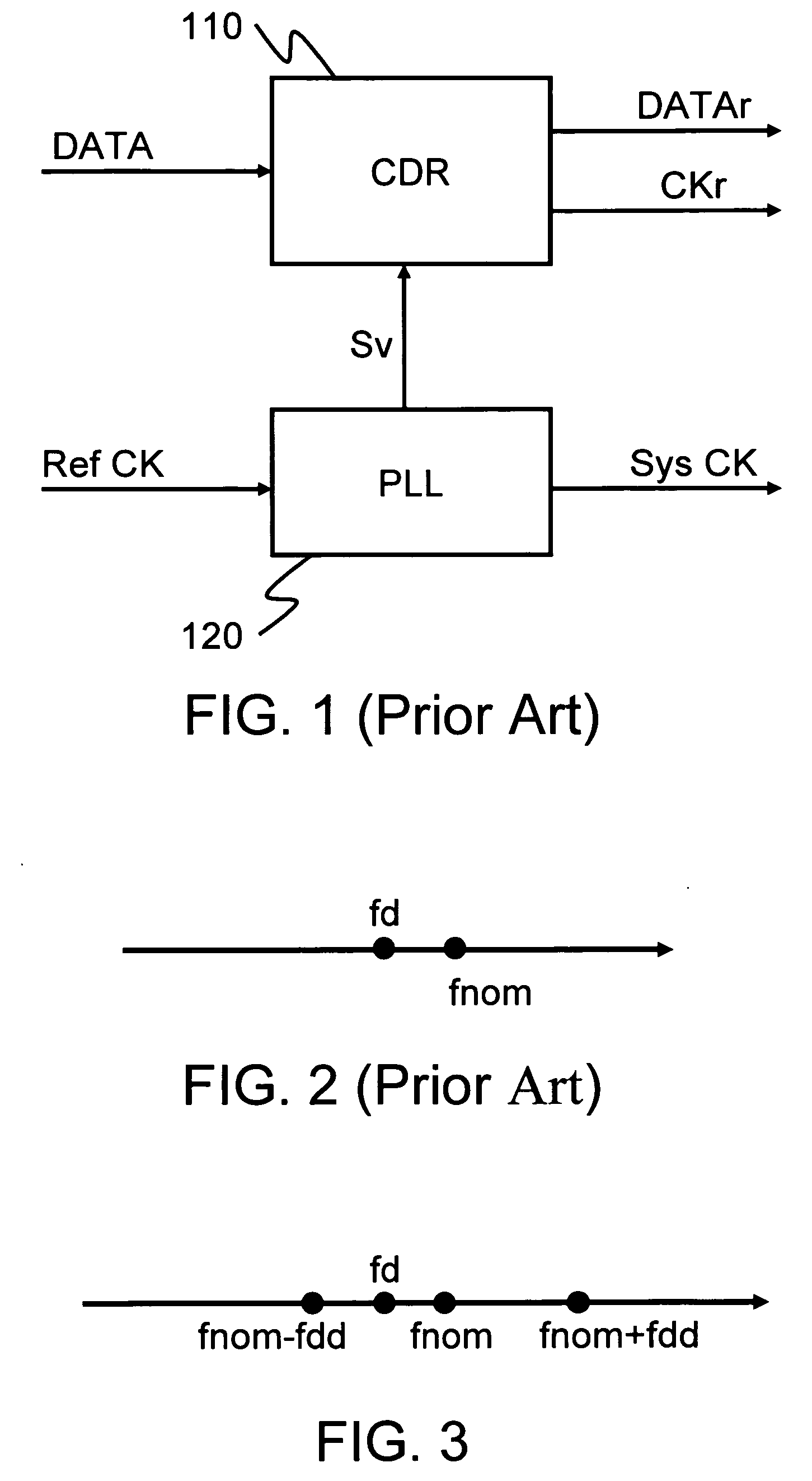
[0037] We first explain the main idea of the invention using FIG. 3. The invention uses a second and a third frequency (fnom±fbb) in the vicinity of the first frequency (fd) to correctly simulate the first frequency. The invention utilizes two major techniques. The oscillator in the CDR circuit can provide two frequencies (fnom±fbb). A controller is used to control the switch between the two frequencies (fnom±fbb) in order to obtain an output frequency almost equal to the first frequency fd. Moreover, the first frequency is a frequency of an incoming data or a recovered data generated previously.

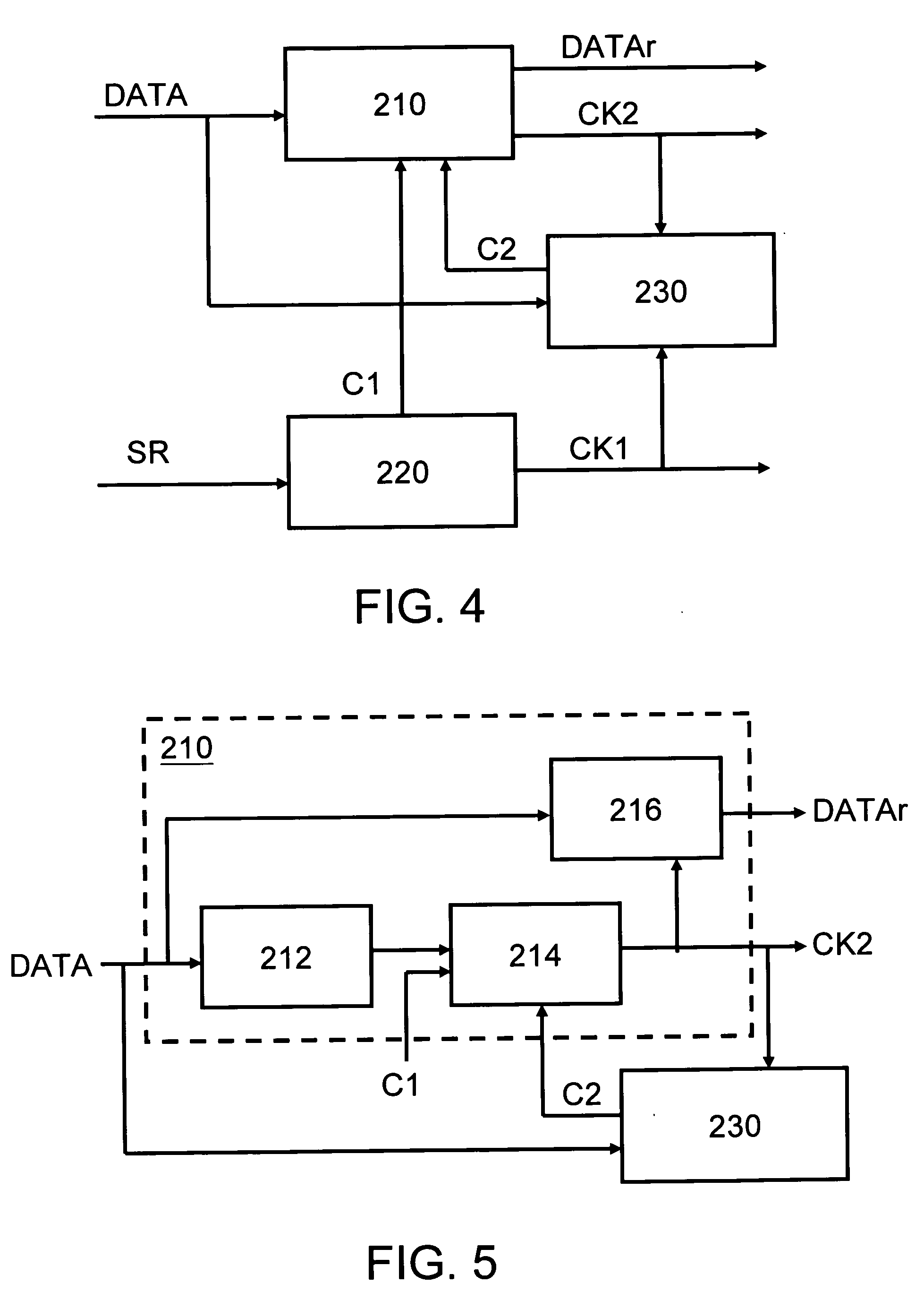
[0038] With reference to FIG. 4, the system according to an embodiment of the disclosed CDR apparatus includes: a CDR circuit 210, a phase-locked circuit 220, and a controller 230.

[0039] The CDR circuit 210, the phase-locked circuit 220, and the controller 230 connect with each other. When the CDR circuit 210 receives an incoming data DATA, the phase-locked circuit 220 generates a first co...


PUM


Abstract

A clock and data recovery apparatus and the method thereof are applied for burst mode clock and data recovery (CDR) in a passive optical network (PON). A phase-locked loop induces a first control signal and a first clock. A clock and data recovery circuit receives an incoming data having a first frequency and induces a second clock having one of second and third frequencies to sample the incoming data according to the second clock to obtain a recovered data, wherein the first frequency is between the second and third frequencies. Moreover, a controller induces a second control signal according to the incoming data (or the recovered data), the first clock, and the second clock to adjust the frequency of the second clock.

Description

BACKGROUND [0001] 1. Field of Invention [0002] The invention relates to a clock and data recovery apparatus and the method thereof, and more particularly to a clock and data recovery apparatus for burst mode clock and data recovery in a passive optical network. [0003] 2. Related Art [0004] During the process of data transmission, a transmitter continuous sends digital signals to a receiver. That is, each bit is transmitted within a fixed time. Therefore, the receiver uses a clock and data recovery (CDR) apparatus to generate a clock corresponding to the incoming data, thereby correctly retiming the incoming data. How to make a clock frequency exactly corresponding to a frequency of the incoming data is a very important issue. [0005] As shown in FIG. 1, a conventional clock and data recovery apparatus includes a clock and data recovery circuit 110 and a phase-locked loop (PLL) 120. The PLL 120 generates a system clock Sys CK according to a reference clock Ref CK, and imposes a voltag...

Claims


Application Information

Patent Timeline
Patent Type & Authority Applications(United States)
IPC IPC(8): H03L7/00H03D3/24H03L7/07H03L7/091H04L7/033
CPCH03L7/07H03L7/0805H03L7/091H04L7/0338
Inventor YU, CHUEH-HAOHUANG, LI-REN
Owner IND TECH RES INST
Why Eureka
Try Eureka