
Aortic stenosis cutting balloon blade

Inactive Publication Date: 2006-06-01
BOSTON SCI SCIMED INC
View PDF39 Cites 30 Cited by
  • Summary
  • Abstract
  • Description
  • Claims
  • Application Information

AI Technical Summary

Benefits of technology

[0009] To reduce the likelihood of inadvertent tissue incision by the distal end of each blade during a movement of the blade, each blade has a blunt tip member at the blade's distal end. The blunt tip member can be attached to the portion of the blade having the cutting edge or integrally formed thereon. For example, in one embodiment of the present invention, the blunt tip member includes a fine coil wire and ball shaped element. More particularly, a fine coil wire having a distal end and a proximal end is provided, with the ball shaped element located at the distal end of the coil wire. In another embodiment of the present invention, the blunt tip member includes a protective sheath. For this embodiment, the cutting edge extends from a cutting edge distal end to a cutting edge proximal end and the protective sheath is positioned to overlay the distal end of the cutting edge. For example, the protective sheath can be made of plastic and bonded to the portion of the blade having the cutting edge. In yet another embodiment, the blunt tip member is formed as a rounded surface to prevent tissue incision by the distal tip of the blade.

Problems solved by technology

For any of several reasons (e.g. aging, or birth defects), it can happen that the aortic valve is somehow damaged and may become stenosed.
This leads to an undesirable heart condition that is commonly known as aortic valve stenosis (AS).
If left untreated, AS can worsen and lead to a number of complications including endocarditis, arrhythmia and in some cases heart failure.
Nevertheless, for many reasons including a high recurrence rate, and despite its initial acceptance, balloon valvuloplasty is now used infrequently and only palliatively or as a bridge to a subsequent valve replacement.

Method used


Image

  • Aortic stenosis cutting balloon blade
  • Aortic stenosis cutting balloon blade
  • Aortic stenosis cutting balloon blade

Examples


Embodiment Construction

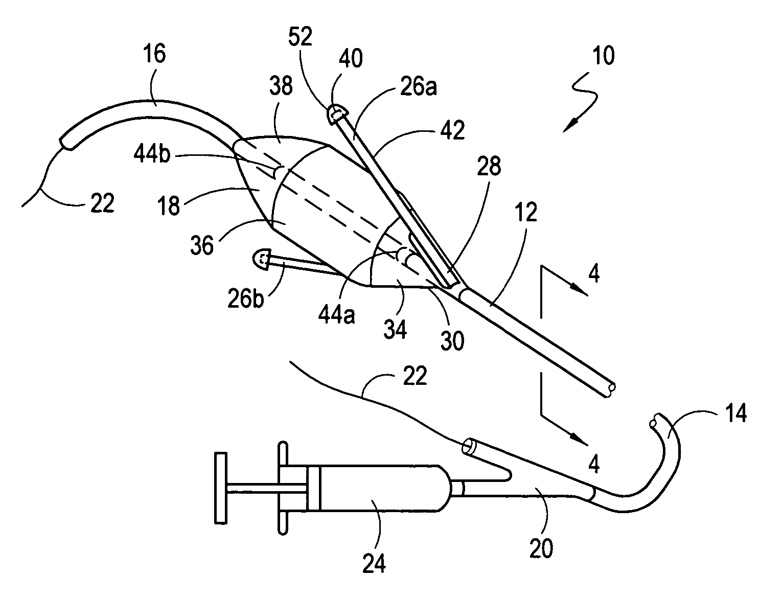
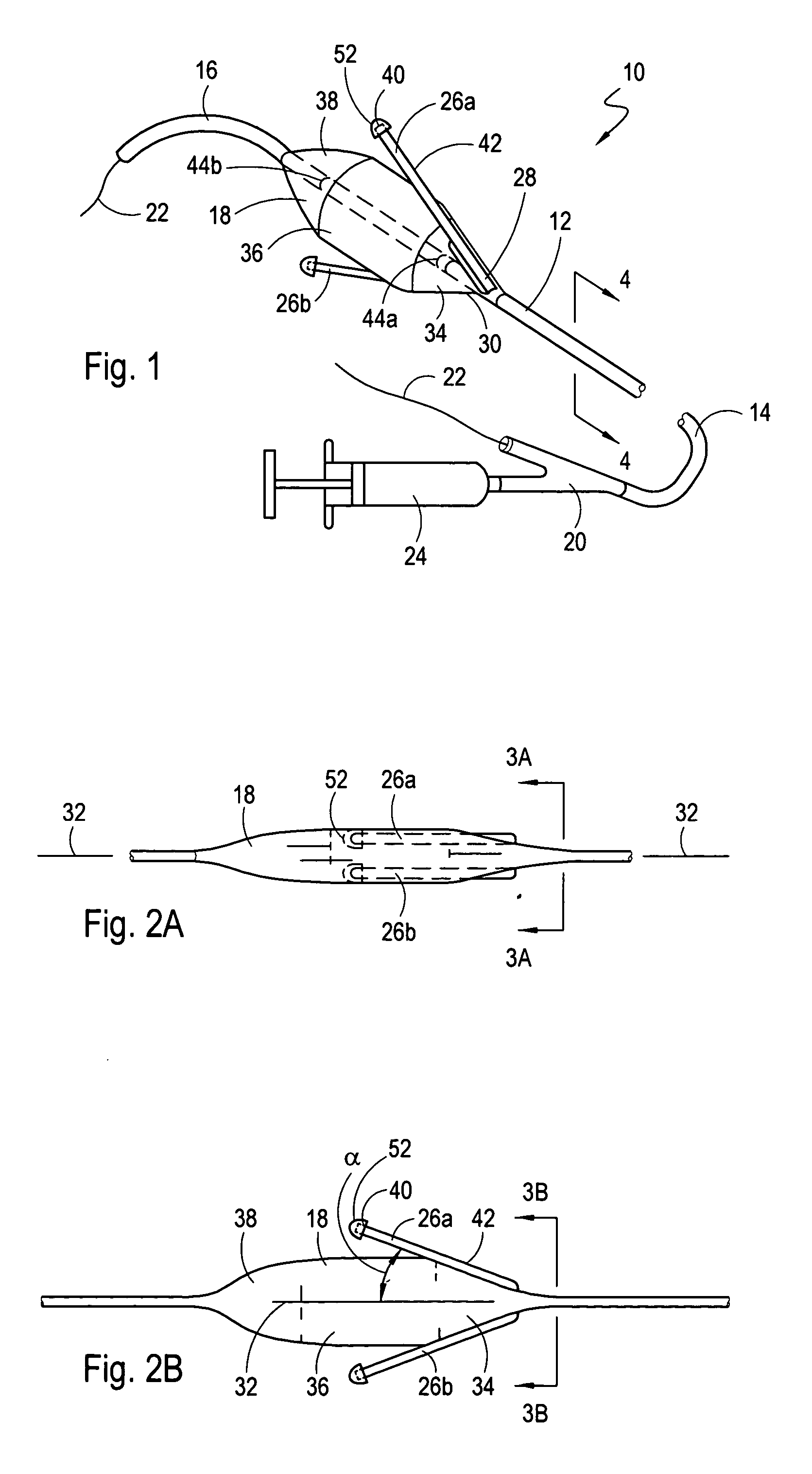
[0025] Referring initially to FIG. 1, a system for incising tissue in accordance with the present invention is shown and generally designated 10. As shown, the system 10 includes a catheter 12 which has a proximal end 14 and a distal end 16. System 10 also has an inflatable, elongated balloon 18 that is mounted on the catheter 12 near its distal end 16. Further, it is seen that a y-site 20 is attached to the proximal end 14 of the catheter 12. Specifically, the y-site 20 allows the catheter 12 to be operationally engaged with a guidewire 22 for the purpose of advancing the catheter 12 over the guidewire 22 after the guidewire 22 has been pre-positioned in the vasculature of a patient (not shown). FIG. 1 also shows that an inflation / deflation device 24 can be connected to the y-site 20 for fluid communication with the balloon 18.

[0026] For the catheter 12, the inflatable balloon 18 can be made of a compliant, semi-compliant or non-compliant material. Specifically, any suitable therm...


PUM


Abstract

A cutting device having a blade for incising internal tissue (e.g. a stenosis) of a patient includes an elongated balloon catheter, with at least one straight blade mounted on the balloon. The blade includes a blunt tip member at the blade's distal end to prevent tissue incision by the blade's distal tip. A proximal portion of the blade is attached to a proximal balloon section, and in operation, the balloon / blade combination is advanced into the vasculature and positioned distal to the stenosis to be incised. The balloon is then inflated. With this inflation, the blade is inclined relative to the axis of the catheter with an increasing distance between the blade and the axis in a distal direction. The device is then withdrawn, proximally, to incise the stenosis. The blunt distal blade tip reduces inadvertent incision of non-target tissue.

Description

FIELD OF THE INVENTION [0001] The present invention pertains generally to interventional medical devices. More particularly, the present invention pertains to catheters that can be used to incise target tissue in the vasculature of a patient while minimizing collateral damage to non-target tissue. The present invention is particularly, but not exclusively, useful for incising an aortic valve stenosis with a catheter having a blade to prevent the inadvertent incision of non-target tissue. BACKGROUND OF THE INVENTION [0002] The aortic valve controls the flow of oxygen-rich blood from the left ventricle into the aorta. Anatomically, the aortic valve consists of three semilunar cusps (i.e. right, left and posterior cusps) that are attached around the circumference of an opening that is located between the aorta and left ventricle. During each heart cycle, the cusps (also called flaps or leaflets) fold back against the inside wall of the aorta as the left ventricle contracts, effectively...

Claims


Application Information

Patent Timeline
IPC IPC(8): A61B17/22
CPCA61B17/22A61B17/320725A61B2017/00292A61B2017/22038A61B2017/22051A61B2017/22061A61B2017/22097
Inventor CROW, LOREN M.
Owner BOSTON SCI SCIMED INC
Features
  • Generate Ideas
  • Intellectual Property
  • Life Sciences
  • Materials
  • Tech Scout
  • Unparalleled Data Quality
  • Higher Quality Content
  • 60% Fewer Hallucinations
Learn More