On-board inert gas generation system

Active Publication Date: 2006-06-08
HAMILTON SUNDSTRAND CORP
View PDF9 Cites 19 Cited by
  • Summary
  • Abstract
  • Description
  • Claims
  • Application Information

AI Technical Summary

Benefits of technology

[0007] An air separation module is fluidly connected to the outlet of the second compressor by a passageway. A vent passage is arranged between the outlet and the air separation module for venting fluid between the outlet and inert separation module. The vent passage enables the flow from the second compressor to be increased at the higher speed thereby increasing the inlet pressure to the air separation module, which enables use of a smaller air separation module.

Problems solved by technology

Lowering the inlet pressure to the module greatly increases its weight.
The electric motor does not utilize all the available electric power to drive the compressor because of compressor rotor blade design limitations.
Because the gap height between the blade and compressor housing is essentially fixed, decreasing the rotor blade height decreases the ratio of rotor blade height to gap height, which causes the efficiency of the compressor to drop to an unknown and unpredictable level, thereby compromising the integrity of the system.

Method used


Image

  • On-board inert gas generation system
  • On-board inert gas generation system

Examples


Embodiment Construction

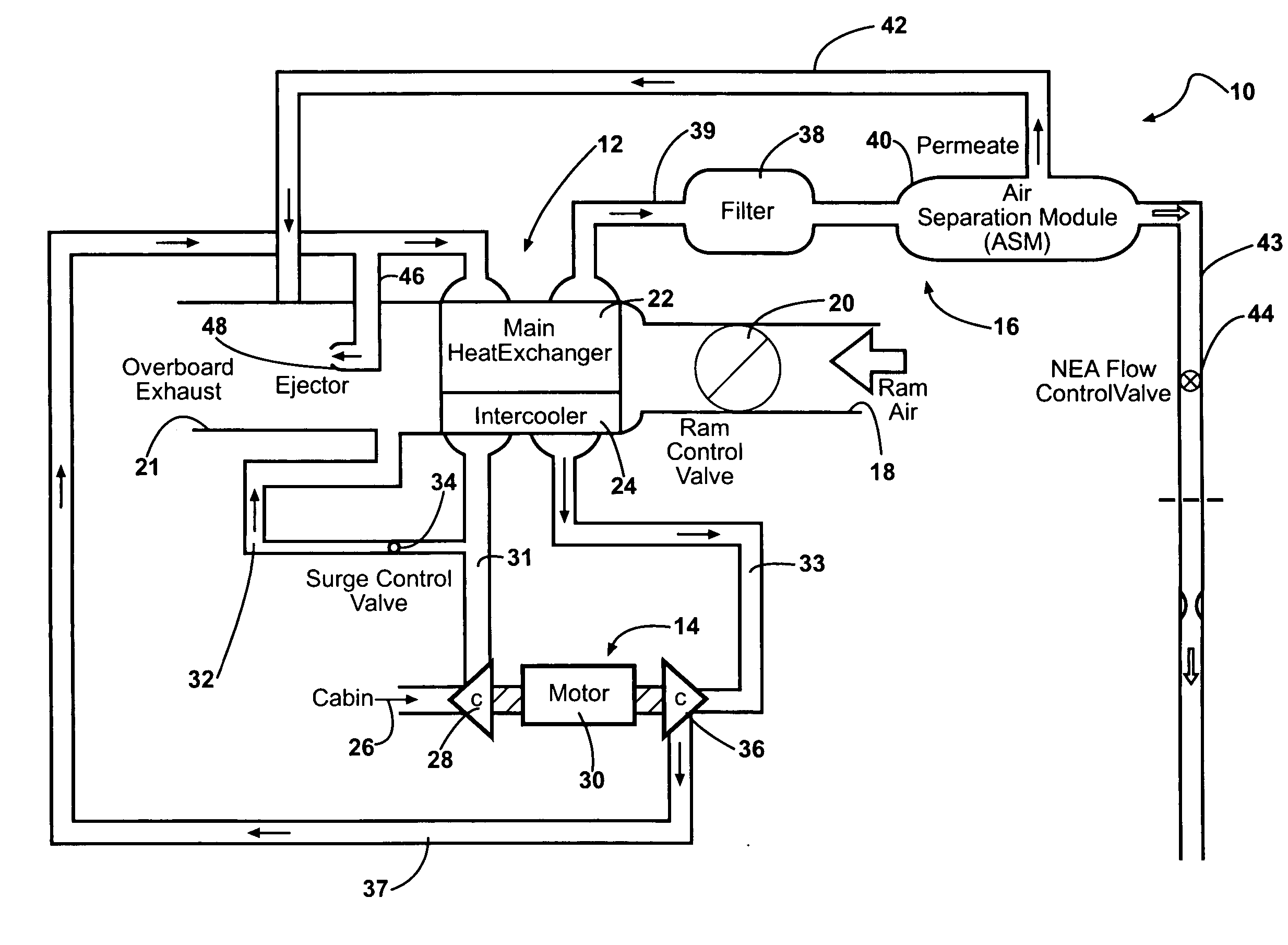
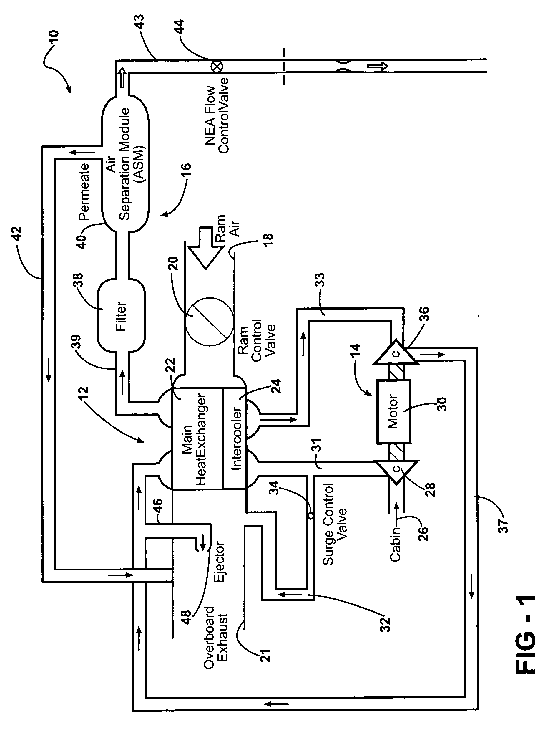
[0012]FIG. 1 is a highly schematic depiction of one example of an inventive on-board inert gas generation system 10. The system 10 includes a heat exchanger system 12 that removes heat generated by compressed air from a compressor system 14. The compressed air provides pressurized air to an air separation module system 16.

[0013] The heat exchanger system 12 is arranged between a ram air inlet duct 18 and a ram air outlet duct 21. Flow through the ram air ducts 18 and 21 is regulated by a control valve 20 arranged between the ram air inlet duct 18 and the heat exchanger system 12.

[0014] Air 26 enters the system 10, for example from the cabin, into a first compressor 28 of the compressor system 14. The first compressor 28 is driven by an electric motor 30. The compressed air exits the first compressor 28 and flows through a passageway 31 through an intercooler 24 of the heat exchanger system 12 where the ram air removes the heat from the compressed air.

[0015] A surge control passag...


PUM

PropertyMeasurementUnit
Pressureaaaaaaaaaa
Flow rateaaaaaaaaaa
Efficiencyaaaaaaaaaa

Abstract

An on-board inert gas generation system provides first and second compressors in fluid communication with one another. The second compressor includes an inlet and an outlet. The inlet is in fluid communication with the first compressor. The second compressor is the final compressor stage of the system. An air separation module is fluidly connected to the outlet of the second compressor by a passageway. A vent passage is arranged between the outlet and the air separation module for venting fluid between the outlet and air separation module. The vent passage enables the flow from the second compressor to be increased thereby increasing compressor efficiency and increasing the inlet pressure to the air separation module, which enables use of a smaller air separation module.

Description

BACKGROUND OF THE INVENTION [0001] This invention relates to an on-board inert gas generation system. Specifically, the invention relates to a method and apparatus for increasing the pressurized air provided to an air separation module of the system. [0002] On-board inert gas generation systems are increasingly used in aircraft to provide inert gas to various locations such as the cargo area or fuel tanks. Typically, the system includes two compressors or stages arranged in series for providing compressed air to the air separation module. It is desirable to provide high pressures to the air separation module to reduce the weight of the module. Lowering the inlet pressure to the module greatly increases its weight. [0003] Centrifugal compressors are typically used in the system to provide compressed air to the module. One proposed system employs an electric motor to drive the compressors. The electric motor does not utilize all the available electric power to drive the compressor bec...

Claims


Application Information

Patent Timeline
IPC IPC(8): B01D53/02
CPCB64D37/32B64D2013/0677Y02T50/44Y02T50/40
Inventor SCHWALM, GREGORY K.
Owner HAMILTON SUNDSTRAND CORP
Why Eureka
Try Eureka