Drive for coverings for architectural openings

a technology for driving covers and openings, applied in the direction of door/window protective devices, shutters/movable grilles, transportation and packaging, etc., can solve the problems of cords in the cord drive, cords may drag on the floor, and are difficult to reach

Active Publication Date: 2006-06-08
HUNTER DOUGLAS INC
View PDF18 Cites 129 Cited by
  • Summary
  • Abstract
  • Description
  • Claims
  • Application Information

AI Technical Summary

Benefits of technology

[0011] The present invention provides a cord drive which has the advantages of prior art cord drives, plus it eliminates many of their problems. One embodiment of the present invention provides a cord drive which does not require the drive cord to travel as far as the window covering. Other embodiments permit the use of a cord drive in unpowered, underpowered, or overpowered blinds and shades.
[0012] In an embodiment involving unpowered window coverings having a drive cord lock, unlocking and releasing the cord lock may allow the covering to lower gradually as the drive cord winds up onto a drive spool, rather than falling precipitously. In some embodiments, the drive cord may automatically lock when it is released to keep the covering in place where it was released, and simply lifting up on the tassel weight attached to the cord may allow the covering to lower gradually, thereby eliminating the need for the operator to move the drive cord sideways to disengage a cord lock. Pulling on the single drive cord may then raise the covering, perhaps with a mechanical advantage, such that the vertical distance the drive cord travels (the stroke) is less than the vertical distance traveled by the window covering. In the case of lightweight window coverings (as compared to the heavier blinds), a spring assist generally is not required to raise or lower the covering, but a spring assist (also referred to as a spring motor) may be used as needed for heavier coverings.
[0015] In certain embodiments of this invention, a spring assisted tilt mechanism mounted on the head rail provides the required force to bias or tilt the slats in one direction, while pulling on a single tilt drive cord tilts the slats in the opposite direction, eliminating the need for two tilt cords.
[0016] Also, in some of the embodiments, the distance traversed by the drive cord to fully raise or lower the window covering is a fraction of the distance traversed by the covering itself. In some embodiments, the distance traversed by the drive cord is 65% or less of the distance traversed by the window covering, while the force required at any point to raise or lower the window covering is as close as possible to 1.5 times the weight of the window covering being raised or lowered. Furthermore, even for large window covering products, the force required at any point to raise or lower the product generally is less than 15 pounds, making it easy for anyone to use.
[0017] Large window covering products or window covering products with heavy components (such as wooden slats in a blind) may require means for transferring the larger forces required to operate the window covering. In some embodiments, V-shaped lift rods are used instead of D-shaped lift rods in order to transfer these larger forces. Furthermore, some embodiments make use of a high strength sleeve along portions of the lift rod to increase the overall strength of the lift rod without increasing the size of the individual drive components. Also, in some embodiments, gearboxes are used to increase the mechanical advantage of the applied force to assist the user in activating the window covering.

Problems solved by technology

The cords in a cord drive, for instance, may be hard to reach when the cord is way up (and the blind is in the fully lowered position), or the cord may drag on the floor when the blind is in the fully raised position.
The cord drive also may be difficult to use, requiring a large amount of force to be applied by the operator, or requiring complicated changes in direction in order to perform various functions such as locking or unlocking the drive cord.

Method used


Image

  • Drive for coverings for architectural openings
  • Drive for coverings for architectural openings
  • Drive for coverings for architectural openings

Examples


first embodiment

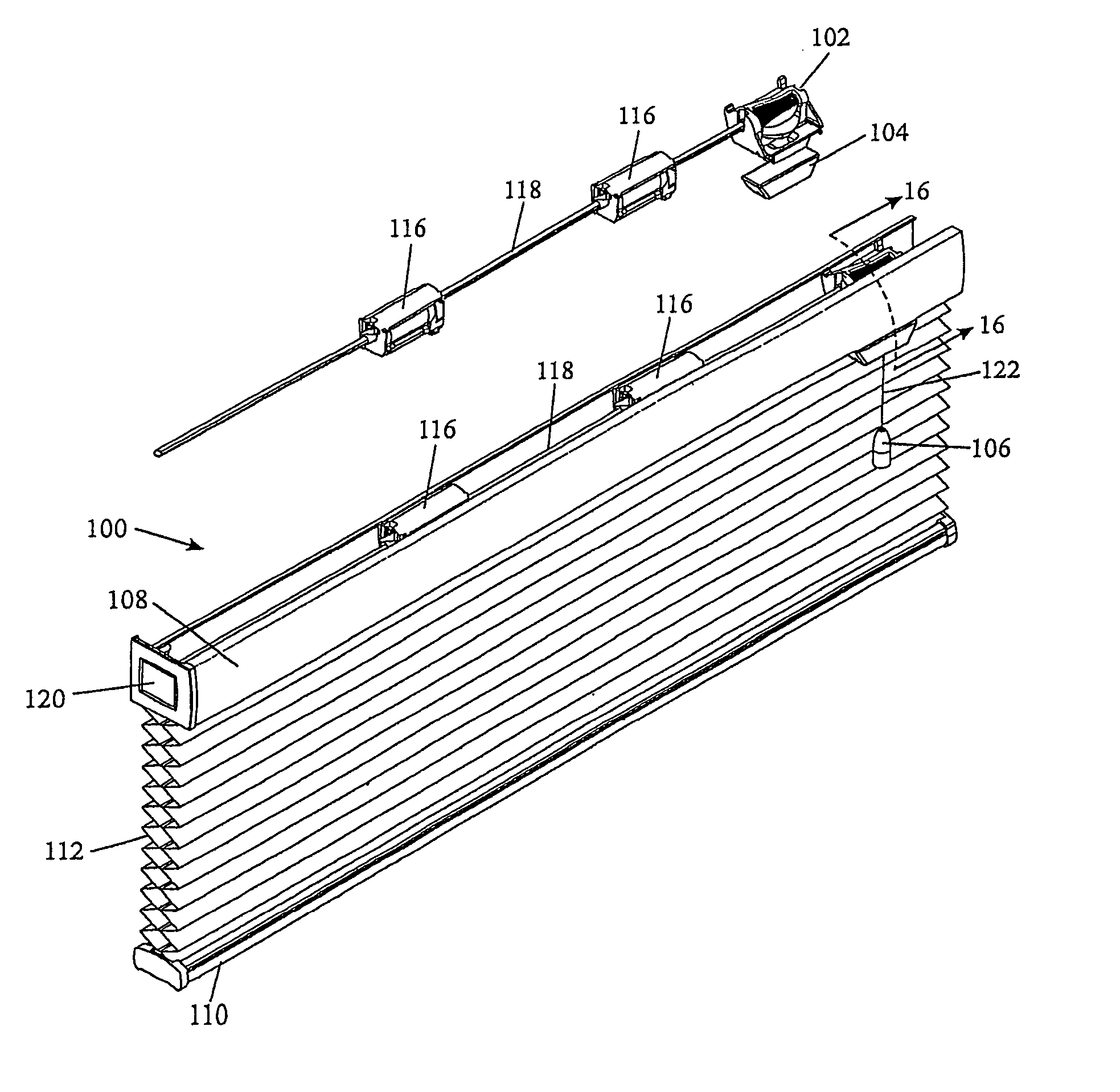
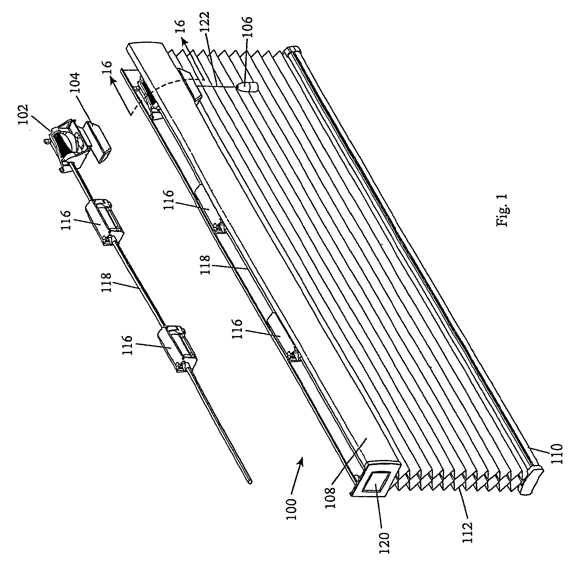
[0230]FIG. 1 is a partially exploded, perspective view of a cellular shade 100 utilizing a cone drive 102 with a roller lock mechanism 104 and a tassel weight 106 (illustrated in further detail in FIGS. 11 through 22) to raise or lower the shade (retracting and extending the expandable material), and to hold the shade in place where the user wants it to remain.

[0231] The shade 100 of FIG. 1 includes a head rail 108, a bottom rail 110, and a cellular shade structure 112 suspended from the head rail 108 and attached to both the head rail 108 and the bottom rail 110. Lift cords 114 (not shown in this view) are attached to the bottom rail 110 and to lift stations 116 such that when the lift rod 118 rotates, the lift spools on the lift stations 116 also rotate, and the lift cords 114 wrap onto or unwrap from the lift stations 116 to raise or lower the bottom rail 110 and thus raise or lower the shade 100. These lift stations 116 and their operating principles are disclosed in U.S. Pat. N...

second embodiment

[0298] Only a relatively small force is required to engage the cord 122 onto the capstan 184 such that no slippage occurs. In the present embodiment, a weight of less than 4 ounces can hold the cord 122 taut onto the capstan 184 even against a 15 pound force acting in the opposite direction to lower the window covering. As explained below with respect to a second embodiment involving a locking dog, this is an important consideration, as only a small frictional force is required of the locking dog to hold the window covering locked in place, and this small force is not enough to fray the drive cord 122.

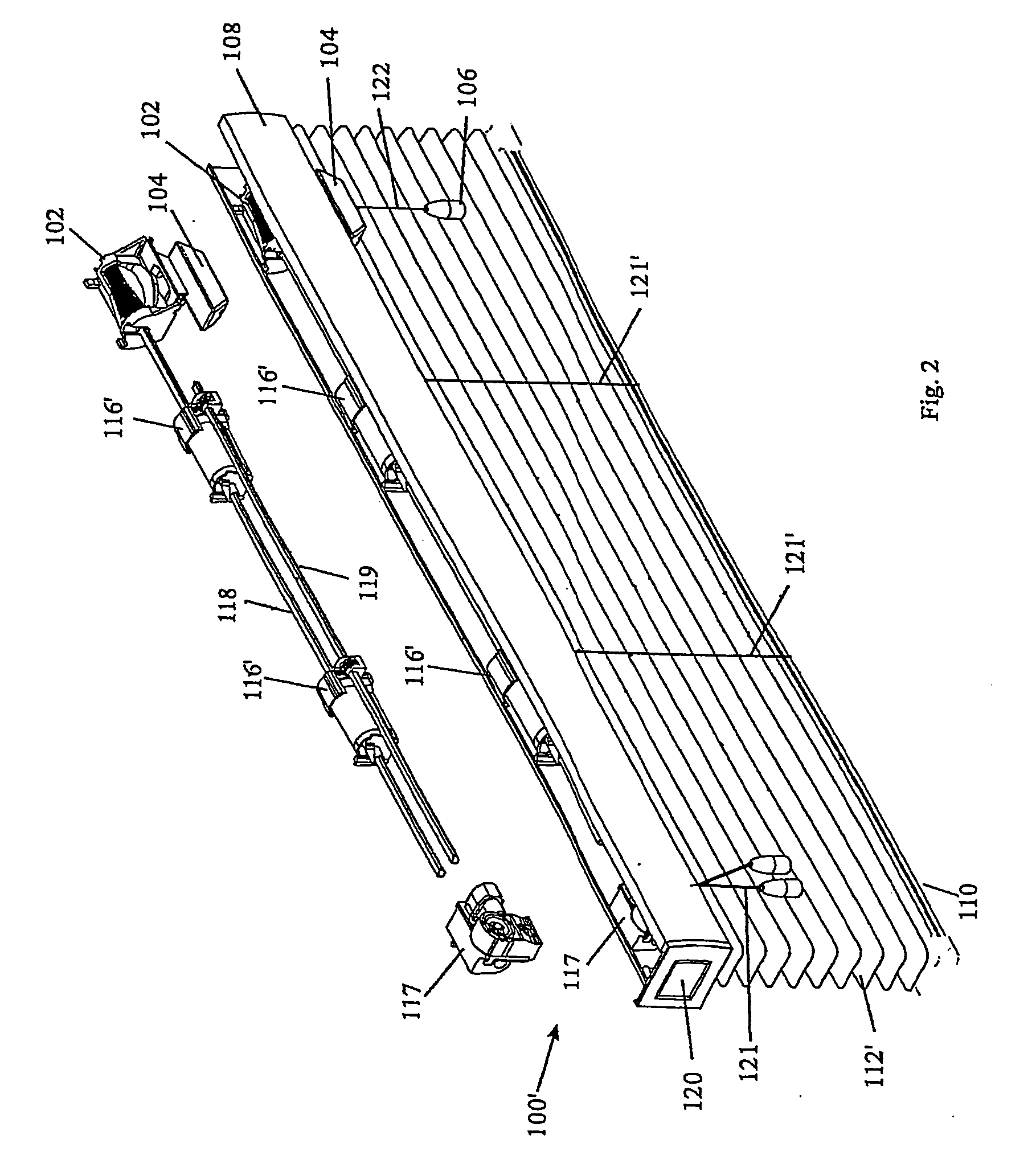
[0299]FIG. 2 shows another embodiment of a window covering 100′ made in accordance with the present invention. In this embodiment, the window covering is a blind 100′, and it includes elements already described with respect to the cellular product 100, such as the cone drive 102, the roller lock mechanism 104, the tassel weight 106, the lift rod 118 and lift and tilt stations 116′ moun...

embodiment 100

[0326] As can be seen in FIG. 43, the wand assembly 284 defines a continuous passageway 322, 312, 304 allowing the drive cord 122 to extend from the handle 286 to the roller lock mechanism 104″. As the handle 286 is pulled down by the operator, the web 318 of the handle pushes apart the projecting legs 310 of the inner extrusion 294, displacing them just far enough apart for the handle 286 to slide through. Since the drive cord 122 is tied off to the bottom of the inner cylindrical portion 320 of the handle 286, the cord 122 is also pulled down, having an effect similar to pulling on the tassel weight 106 in the first window covering embodiment 100 discussed earlier.

[0327] Pulling down on the handle 286 causes the roller lock 132 to shift down, allowing it to rotate freely. The drive cord 122 wraps onto and unwraps from the capstan 184 as the roller lock 132 rotates, and the cord 122 unwraps from the drive cone 124, causing the drive cone 124 and the lift rod 118 to rotate. This cau...


PUM


Abstract

A cord drive mechanism to convert linear motion to circular motion for use in coverings for architectural openings. Various controls are used to provide a braking force on the cord. Some of the embodiments incorporate a capstan.

Description

[0001] This is a continuation-in-part of PCT application PCT / US 04 / 22694 filed Jul. 15, 2004, which claims priority from U.S. Provisional Application Ser. No. 60 / 448,208, filed Jul. 16, 2003, both of which are hereby incorporated herein by reference.BACKGROUND OF THE INVENTION [0002] The present invention relates to a cord drive which can be used for opening and closing or tilting coverings for architectural openings such as Venetian blinds, pleated shades, vertical blinds, other expandable materials, and other mechanical devices. [0003] Typically, a blind transport system will have a head rail which both supports the blind and hides the mechanisms used to raise and lower or open and close the blind. Such a blind system is described in U.S. Pat. No. 6,536,503, Modular Transport System for Coverings for Architectural Openings, which is hereby incorporated herein by reference. In the typical top / down product, the raising and lowering of the blind is done by a lift cord or lift cords s...

Claims


Application Information

Patent Timeline
Patent Type & Authority Applications(United States)
IPC IPC(8): A47H5/00B65GE06B9/322
CPCE06B9/262E06B9/322E06B9/324E06B9/80E06B2009/3227E06B2009/807E06B2009/3225B65G1/00
Inventor ANDERSON, RICHARDFISHER, ROBERT E. IIFRASER, DONALD E.HAARER, STEVEN R.
Owner HUNTER DOUGLAS INC
Why Eureka
Try Eureka