Controlled cooling methods and apparatus for laser sintering part-cake

a laser sintering and cooling method technology, applied in the direction of additive manufacturing processes, electric/magnetic/electromagnetic heating, manufacturing tools, etc., can solve the problems of reducing the efficiency of the laser sintering process, increasing the cooling time, and comparatively poor thermal conductivity of the common laser sintering materials. to achieve the effect of transferring heat away

Active Publication Date: 2006-06-08
3D SYST INC
View PDF40 Cites 160 Cited by
  • Summary
  • Abstract
  • Description
  • Claims
  • Application Information

AI Technical Summary

Benefits of technology

[0011] According to another embodiment of the invention, there is provided a method for controlling the cooling rate of at least a portion of a part-cake having therein unfused powder and one or more built parts, the method comprising selectively forming one or more cooling fins comprising fused powder in at least a portion of the part-cake. Preferentially, the cooling fins are at least partially conformal with the built parts within the part-cake, being selectively positioned for effectively transferring heat away from the parts to the top surface of the part-cake. In one particular embodiment, the ends of the cooling fins at the top surface of the part-cake are attached to an external heat exchange apparatus for further heat removal.

Problems solved by technology

Powder materials commonly used in laser sintering have comparatively poor thermal conductivity and so can take a long time to cool down to workable temperatures, particularly at the interior portions of the part-cake.
The increased cool-down time reduces efficiency of the laser sintering process by increasing the residence time for each part build session, thereby decreasing throughput of the laser sintering system.
The cool down portion of the laser sintering process can be detrimental to the built parts if the cooling is non-uniform throughout the part-cake causing uncontrolled thermal gradients therein.
Non-uniform cooling can lead to unacceptable geometric distortions of the built parts in the part-cake, as well as inconsistent mechanical properties of the built parts.

Method used


Image

  • Controlled cooling methods and apparatus for laser sintering part-cake
  • Controlled cooling methods and apparatus for laser sintering part-cake
  • Controlled cooling methods and apparatus for laser sintering part-cake

Examples


Embodiment Construction

[0029] The invention now will be described more fully hereinafter with reference to the accompanying drawings, in which preferred embodiments of the invention are shown. These embodiments are provided so that this disclosure will be thorough and complete, and will fully convey the scope of the invention to those skilled in the art.

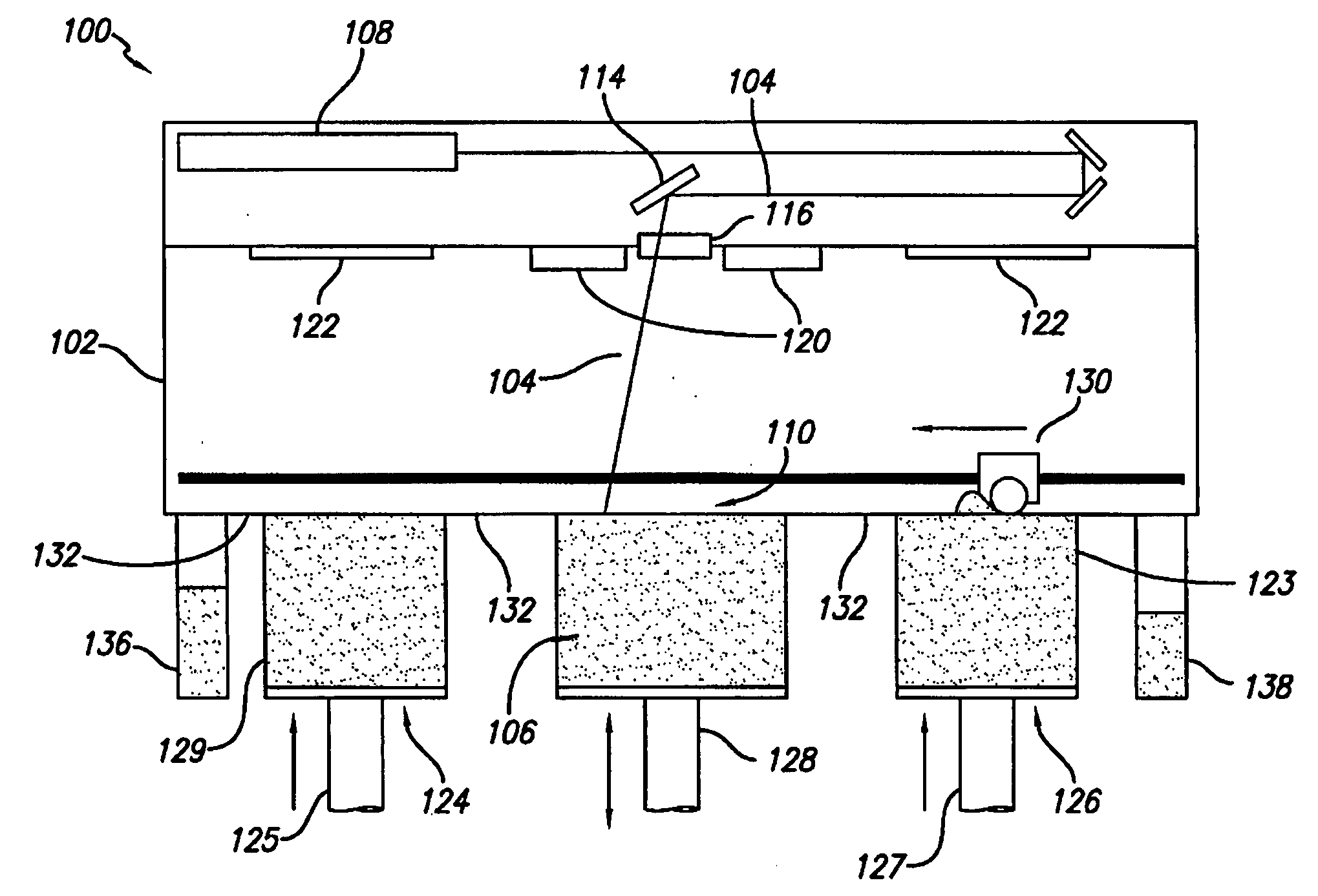
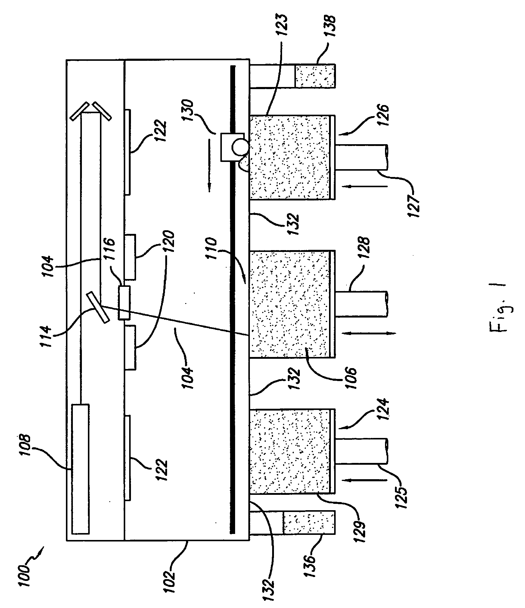
[0030] The invention is directed to methods and apparatus for selectively controlling the cooling rate of a part-cake in a laser sintering process. FIG. 1 illustrates a conventional selective laser sintering system currently sold by 3D Systems, Inc. (Valencia, Calif.). In FIG. 1, a front view of the apparatus is provided with the outer covering of the apparatus cut away to show the working parts of the system. Generally, a carbon dioxide laser and its associated optics is shown mounted in a unit above a process chamber that includes a powder bed, two feed powder cylinders, and a leveling roller. The process chamber maintains the appropriate temperature an...


PUM

PropertyMeasurementUnit
thicknessaaaaaaaaaa
thicknessaaaaaaaaaa
thicknessaaaaaaaaaa

Abstract

The invention is a method for controllably cooling at least a portion of a part-cake from a laser sintering system to minimize cool down time, maximize throughput, and minimize thermal gradients within the part-cake. The method generally comprises forming one or more thermal transfer channels within the part-cake. The thermal transfer channels can include ducts and cooling fins in the part-cake surrounding the formed part. The method can further comprise removing unfused powder from the ducts and introducing cooling media into the ducts. The invention also includes a part-cake having thermal transfer channels formed therein and a laser sintering apparatus comprising a part-cake containing cylinder having permanent fittings therein for receiving terminal portions of thermal transfer channels formed in the part-cake.

Description

FIELD OF THE INVENTION [0001] The invention is directed to a method and apparatus for controlling the cooling rate of a part-cake in a laser sintering apparatus, the part-cake containing unfused powder and built parts of fused powder. BACKGROUND [0002] Solid freeform fabrication processes are increasingly used for producing freeform, complex geometry components. In particular, selective laser sintering is useful for creating three dimensional objects directly from digital data (e.g., computer-aided-design (CAD) databases, medical scan imaging files, etc.) in an automated fashion. An object is created through a sequential fusion buildup of cross sections of the finished part from a starting powder. The powder is fused with a scanning laser beam one layer at a time, and each scanned layer corresponds to a cross section of the final object's mathematically sectioned digital data model. [0003] Detailed descriptions of selective laser sintering technology are provided in U.S. Pat. Nos. 4...

Claims


Application Information

Patent Timeline
Patent Type & Authority Applications(United States)
IPC IPC(8): B23K26/00
CPCB22F3/1028B22F3/1055B22F2999/00B29C35/16B29C67/0077B29C2035/0838B29C2035/1616B29C2035/1658B22F5/10B22F2003/1056B29C64/153B22F2005/103B33Y40/00Y02P10/25B22F10/28B22F12/20B22F12/49B22F10/73
Inventor CHUNG, TAE MARKBISHOP, RAYMOND J.GEVING, BRADLEY DAVIDFONG, JON JODYDUNNE, PATRICK
Owner 3D SYST INC
Why Eureka
Try Eureka