Light-emitting diode, led light, and light apparatus

a technology of led light and light-emitting diodes, which is applied in the direction of lighting and heating apparatus, discharge tube luminescnet screens, fixed installations, etc., can solve the problems of external radiation efficiency, difficult to provide a low-profile light source, and appearance spoilage, and achieve high external radiation efficiency, high efficiency, and low cost

Inactive Publication Date: 2006-06-08
TOYODA GOSEI CO LTD
View PDF6 Cites 108 Cited by
  • Summary
  • Abstract
  • Description
  • Claims
  • Application Information

AI Technical Summary

Benefits of technology

[0053] the lead frame that is protruded out of the transparent resin while being bent under its mount surface from the vicinity of a mount position of the light emitting element so as to reduce part of the lead frame sealed with the transparent resin as much as possible.

Problems solved by technology

Further, if it is tried to forcedly make it low-profile, its appearance is spoiled.
Therefore, there is a problem that it is difficult to provide a low-profile light source which is a characteristic of LED.
Thus, there is a further problem in external radiation efficiency.
However, in the LED light, there is a problem that light directly radiated from the light source 1100 cannot be taken out in the perpendicular direction because of being blocked by the first reflection surface 1110 disposed over the light source 1100 and, therefore, a dark portion is generated at the center.
However, in the above LED light, there is a problem that the entire thickness must be increased since there is provided the dome section 1610 to converge light radiated from the light source 1620 to the center axis.
Further, it is difficult to perfectly align the center axis of lens element 1740 with the center axis of light source 1620 in fabrication and, therefore, a deviation in position may occur and uniformity in brightness is difficult to obtain over all directions.
As described above, it has a potential problem that the structure of light source 1620 itself may cause a difference in light distribution characteristic.
In addition, due to a deviation in position in mounting the lens element 1740 separately prepared, there occurs a problem that the amount of reflected light in all reflection directions given by the first reflection region 1640 becomes uneven.
Further, there are problems that the light utilization efficiency lowers due to sideward light not enabled to be focused on the center axis by the dome section 1610 and that the radiation area cannot be therefore enlarged.
Thus, the light utilization efficiency lowers.
Therefore, loss of light is generated in that air layer or at the interface.
Still further, due to the separate preparation, a deviation in position may occur when being subjected to a physical shock.
Therefore, it is difficult to design an optical system that the light emitting element and reflection mirror is close to each other.
Further, there are problems that the number of parts or fabrication steps increases and that variation of precision in fabrication increases.
Accordingly, even when a lamp such as an automobile brake lamp-integrated tail lamp is manufactured by using such LED lights, the proper brightness of light source cannot be utilized due to the above problems.
Because of this, the lamp appears dark as a whole and lacks a degree of freedom in appearance.

Method used


Image

  • Light-emitting diode, led light, and light apparatus
  • Light-emitting diode, led light, and light apparatus
  • Light-emitting diode, led light, and light apparatus

Examples


embodiment 1a

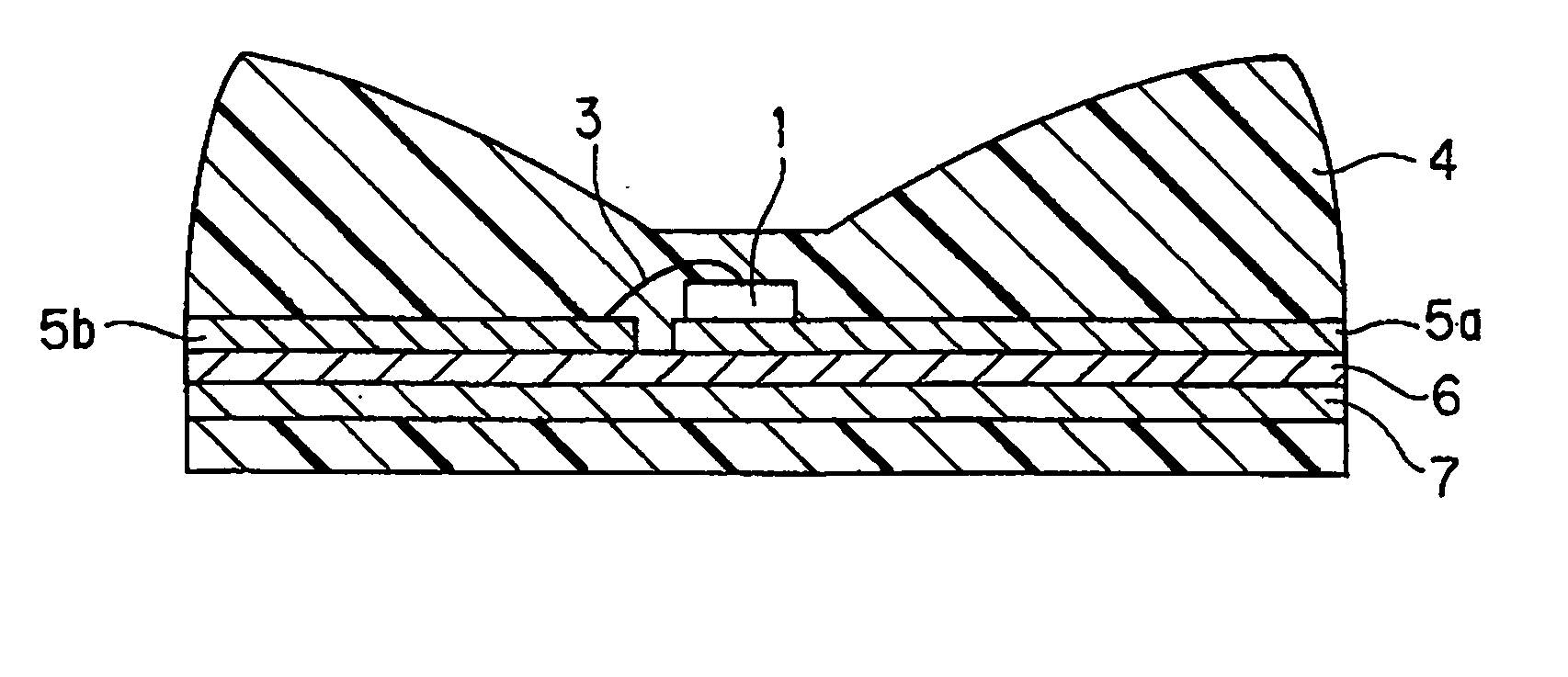
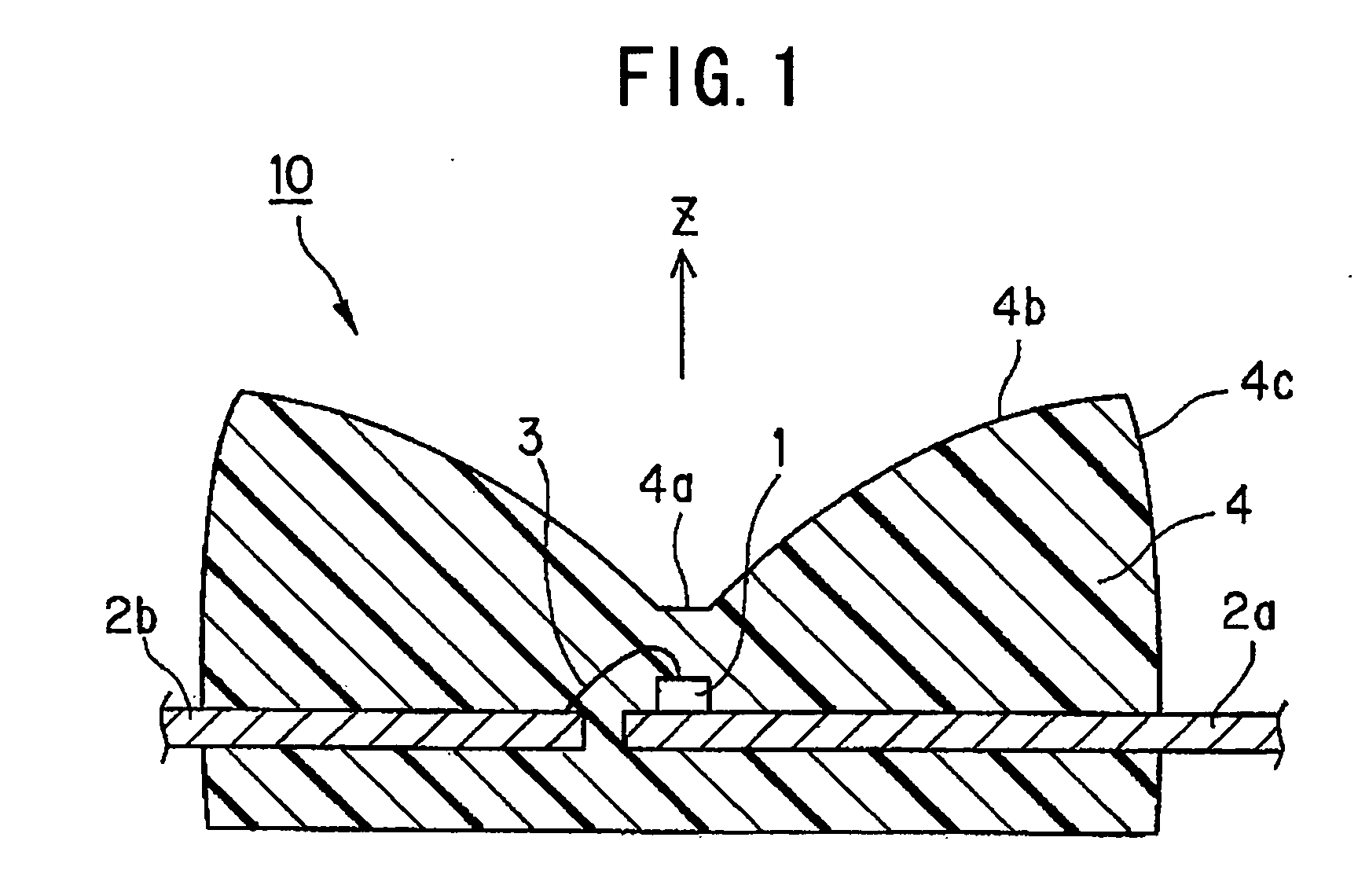
[0225] At first, a light emitting diode in embodiment 1A of the invention will be explained with reference to FIG. 1 and FIG. 2. As shown in FIG. 1, the light emitting diode 10 has a light emitting element 1 that has dimensions of 400×400 μm and is mounted through Ag paste (not shown) on a lead frame 2a. The light emitting element 1 has an electrode, which has a diameter of 0.1 mm and is formed on the center of emission surface, and a gold wire ball (not shown) formed thereon that are electrically connected through a wire 3 with a diameter of 30 μm to a lead 2b with an opposite polarity. These are sealed with transparent resin 4 and the optical surface is molded.

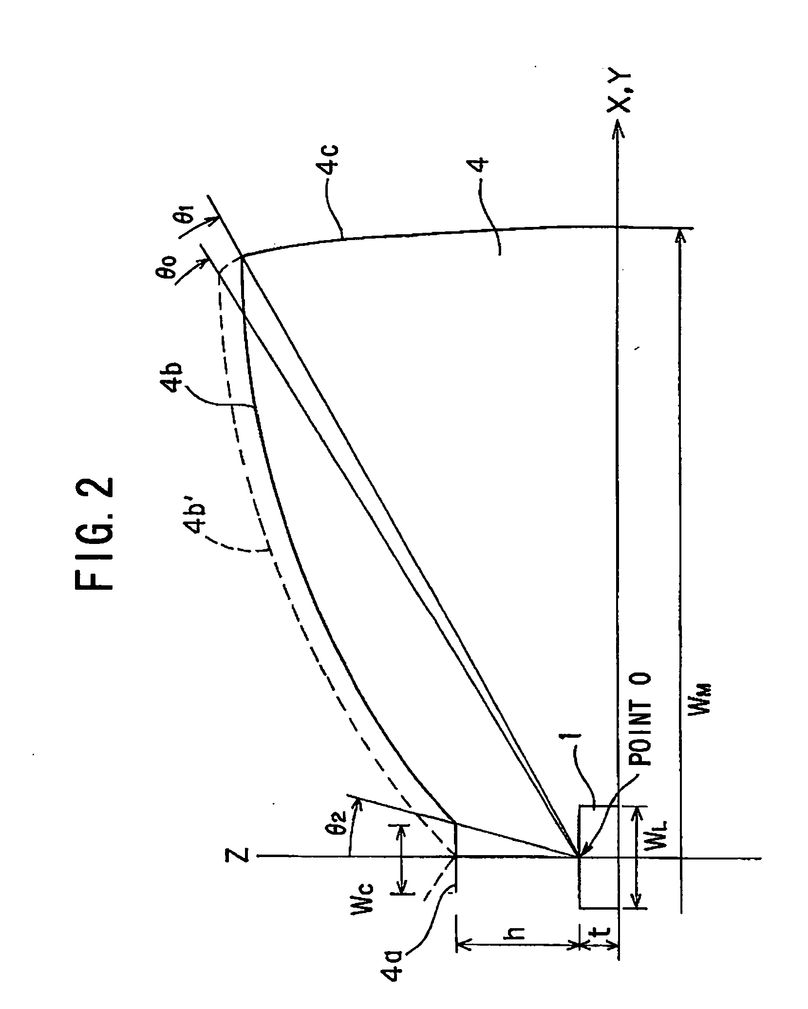
[0226] As shown in FIG. 2, the optical surface is composed of a central radiation surface 4a, an upper reflection surface 4b and a side radiation surface 4c. The central radiation surface 4a is h=0.5 mm above the upper surface of light emitting element 1 and is in the shape of a cylinder with a diameter of Wc=0.3 mm. The up...

embodiment 1b

[0239] Embodiment 1B of the invention will be explained with reference to FIG. 11 to FIG. 19.

[0240] As shown in FIG. 11, an LED light 31 in embodiment 1B of the invention is constructed such that the light emitting diode (LED) in embodiment 1A is, as a light source, mounted at the center of a circular body and is surrounded by a reflection mirror 33, as a second reflection mirror, which is formed concentric and stepwise. Herein, the center axis of light emitting element is defined as a Z-axis, and its origin is at the upper surface of light emitting element and an X-axis and a Y-axis intersect at right angles at the origin. These definitions are applied to modifications and embodiments described below as well.

[0241] As shown in FIG. 11 (c), a reflection surface 33a of the reflection mirror 33 is about 45 degrees inclined to the X-Y plane. The reflection mirror 33 is made by molding acrylic resin and then being formed of the reflection surface by aluminum evaporation.

[0242] Then, ...

modification 1

[Modification 1]

[0247] As shown in FIG. 14, the first modification of the LED light 31 in embodiment 1B may be composed such that a pair of lead plates 42a, 42b are caved only around the light emitting element 36 to provide a third reflection mirror. Thereby, although in the basic form in FIG. 12 light is radiated directly upward only from directly over the light emitting element 36, light can be also radiated upward from around the light emitting element 36 in LED. Thus, it further appears the entire portion emits light and, thereby, the appearance can be enhanced.


PUM


Abstract

An LED light comprising a light-emitting device provided to power supply means, encapsulating means for encapsulating the light-emitting device with a light-transmitting material, a reflective surface for reflecting the light emitted from the light-emitting device to a direction perpendicular to the center axis of the light-emitting device or at a large angle to the center axis, opposed to the light-emitting surface of the light-emitting device, a light-emitting diode having a side directing surface for directing sideways the light reflected from the reflective surface to a direction perpendicular to the center axis of the light-emitting device or at a large angle to the center axis, and a reflecting mirror disposed around the light-emitting diode.

Description

TECHNICAL FIELD [0001] This invention relates to a package resin (hereinafter also referred to as light emitting diode or LED) with a light emitting element (hereinafter also referred to as LED chip) installed therein, and an LED light (hereinafter also referred to as light emitting unit) that the LED is used as a light source, and a lamp that is composed using the LED light and can be applied as an automobile tail lamp or stop lamp etc. BACKGROUND ART [0002] Along with the development of high-brightness light emitting element, an LED light using LED as a light source is progressively used for an automobile rear lamp etc. LED offers a good visibility due to its sharp spectrum. Also, it has a high signaling speed to a following vehicle since the response speed is high, and it has a significant effect in reducing the braking distance in the case of high-speed driving. Further, since LED itself is a monochromatic light source, it is not necessary to cut light color other than desired c...

Claims


Application Information

Patent Timeline
Patent Type & Authority Applications(United States)
IPC IPC(8): H01L33/00H01J1/62B60Q1/26F21K99/00F21S8/10F21V5/00H01L33/54H01L33/60H01L33/62
CPCB60Q1/2696F21V5/008F21K9/68F21S43/14F21S43/26F21V5/10H01L33/54H01L33/60H01L33/62H01L2224/45144H01L2224/48091H01L2224/48247H01L2224/8592H01L2924/181H01L2924/1815H05K2201/10106H01L2924/00014H01L2924/00012
Inventor SUEHIRO, YOSHINOBUMISAWA, AKIHIROTAKAHASHI, TOSHINORIOTA, HISATOSHIOTA, KOICHIOKANO, JUNKO
Owner TOYODA GOSEI CO LTD
Why Eureka
Try Eureka