Electro-optic crystal, diffraction-based, beam-steering element

a technology of diffraction-based beam steering and electro-optic crystals, applied in non-linear optics, instruments, optics, etc., can solve the problems of reducing diffraction efficiency, limited performance of a single element that uses liquid crystal techniques, and limitation of the steering angle of liquid crystal techniques, so as to improve diffraction efficiency

Active Publication Date: 2006-06-08
NORTHROP GRUMMAN SYST CORP
View PDF4 Cites 17 Cited by
  • Summary
  • Abstract
  • Description
  • Claims
  • Application Information

AI Technical Summary

Benefits of technology

[0010] A beam-steering element made of a more optically-active material with an improved diffraction efficiency is provided. The beam-steering element comprises a plurality of electrode layers and one electro-optic crystal layer interposed between every two adjacent electrode layers. Each electro-optic crystal layer and the electrode layer adjacent thereto have an aspect ratio of about 1:1. The electrode layers and the optic crystal layers are interposed between two substrates. That is, the substrates must be transparent, particularly to an incoming optical beam to be modulated by the electro-optic crystal layer. In one embodiment, the incoming optical beam includes at least one optical beam having a wavelength of about 1.55 microns. The electrode layers are also transparent to the optical beam to be modulated by the electro-

Problems solved by technology

Currently, the performance of a single element that uses the liquid-crystal techniques is limited to a steering angle of about ±3o with 50% diffraction efficiency and 1 msec frame-refresh rates.
As understood, the limitation of steering angle for liquid-crystal techniques is caused by the fly-back problem that reduces the diffraction efficiency.
However, due to the diffraction inefficiency in real practice, the steering angle provided by such device is only about ±3o.
The fly-back problem was found to be the result of lack of “crispness” in the spatial phases resets.
That is, because of field fringing, the index of refraction gradient is not sharp enough at a given phase reset to facil

Method used


Image

  • Electro-optic crystal, diffraction-based, beam-steering element
  • Electro-optic crystal, diffraction-based, beam-steering element
  • Electro-optic crystal, diffraction-based, beam-steering element

Examples


Embodiment Construction

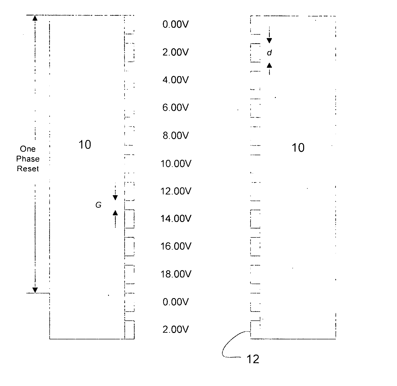
[0028] Potassium tantalate niobate (KTN) has been known to be a highly optically-active material since 1960's, but the application of potassium tantalate niobate has been very limited because the difficulty for fabrication. Potassium tantalate niobate is strongly dependent on temperature. In certain scenarios, the electro-optic coefficient of potassium tantalate niobate rc can reach as high as about 1800 pm / V, which is about 60 times more than the analogous electro-optic coefficient for lithium niobate (LiNbO3). The index of refraction of potassium tantalate niobate can be modulated with an applied voltage as: Δ⁢ ⁢n=nc32⁢rc⁢Ez,(1)

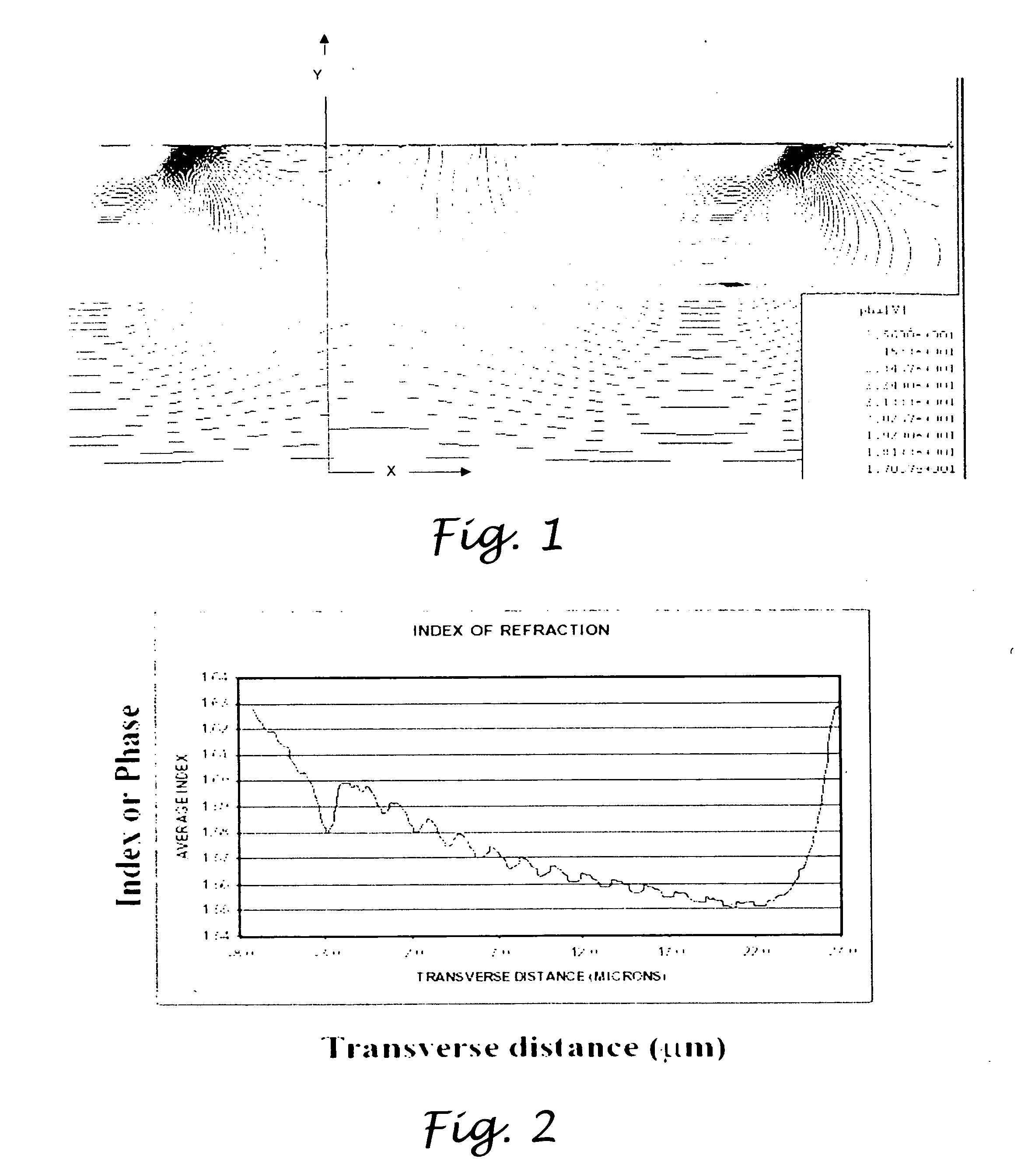
where nc=2.277, and Ez is the applied voltage. The difference of index of refraction results in an optical-path length OPL(x) of an optical beam propagating through the potassium tantalate niobate medium as:

OPL(t,x)=∫0ln(y)dy  (2),

where l is the thickness of the potassium tantalate niobate medium. The optical-path difference OPD(t,x) can then be obtain...


PUM


Abstract

A beam-steering element made of a more optically-active material, potassium tantalate niobate, with an improved diffraction efficiency, having a plurality of electrode layers and one electro-optic crystal layer interposed between every two adjacent electrode layers. Each electro-optic crystal layer and the electrode layer adjacent thereto have an aspect ratio of about 1:1. The electrode layers and the electro-optic crystal layers are interposed between two substrates. Preferably, the substrates are transparent to an incoming beam to be modulated by the electro-optic crystal layer.

Description

CROSS-REFERENCE TO RELATED APPLICATIONS [0001] Not Applicable STATEMENT RE: FEDERALLY SPONSORED RESEARCH / DEVELOPMENT [0002] Not Applicable BACKGROUND OF THE INVENTION [0003] The present invention relates in general to an agile beam steering device and a method of fabricating the same, and more particular, to a diffraction-based beam-steering device made of electro-optic (EO) material. [0004] Liquid-crystal techniques have been applied to the development of agile, dynamic-grating-based, that is, diffraction-based, beam-steering elements in recent years. Currently, the performance of a single element that uses the liquid-crystal techniques is limited to a steering angle of about ±3o with 50% diffraction efficiency and 1 msec frame-refresh rates. [0005] As understood, the limitation of steering angle for liquid-crystal techniques is caused by the fly-back problem that reduces the diffraction efficiency. For example, Serati et al. has disclosed a device that can provide a theoretical st...

Claims


Application Information

Patent Timeline
IPC IPC(8): G02F1/00
CPCG02F1/292G02F2201/12
Inventor CICCHIELLO, JAMES M.HARKRIDER, CURTIS J.KREISCHER, KENNETH E.GALLAGHER, DAVID A.
Owner NORTHROP GRUMMAN SYST CORP
Why Eureka
Try Eureka