System and method for crest factor reduction

Active Publication Date: 2006-06-08
MICROELECTRONICS TECH INC
View PDF12 Cites 12 Cited by
  • Summary
  • Abstract
  • Description
  • Claims
  • Application Information

AI Technical Summary

Benefits of technology

[0011] The need in the art is addressed by the crest reduction system and method of the present invention. In a most general embodiment, the inventive system includes a first circuit for suppressing peak amplitudes

Problems solved by technology

A challenge for MCPA signal transmission is due to the fact that the combined signal has a high crest factor (ratio of peak power to average power), where the peak power is significantly higher than the average power.
A small portion of the combined signal can have very high peaks and when transmitted at high PA efficiency, these high-level signals reach into the saturated region of the PA's transfer function and the output of the PA has high intermodulation distortion (IMD).
To maintain low ACPR without any linearization techniques, the transmit signal level must be decreased sufficiently so that the peak amplitudes are not in the saturated zone of the PA, but this reduces the amplifier efficiency.
However, it is difficult to generate signals with low crest factor and low ACPR inasmuch as limiting the amplitude increases out of band emissions (e.g. sidelobes) and thereby raises the ACPR level.
This adds to the complexity, storage requirements and cost of the system.

Method used


Image

  • System and method for crest factor reduction
  • System and method for crest factor reduction
  • System and method for crest factor reduction

Examples


Embodiment Construction

[0032] Illustrative embodiments and exemplary applications will now be described with reference to the accompanying drawings to disclose the advantageous teachings of the present invention.

[0033] While the present invention is described herein with reference to illustrative embodiments for particular applications, it should be understood that the invention is not limited thereto. Those having ordinary skill in the art and access to the teachings provided herein will recognize additional modifications, applications, and embodiments within the scope thereof and additional fields in which the present invention would be of significant utility.

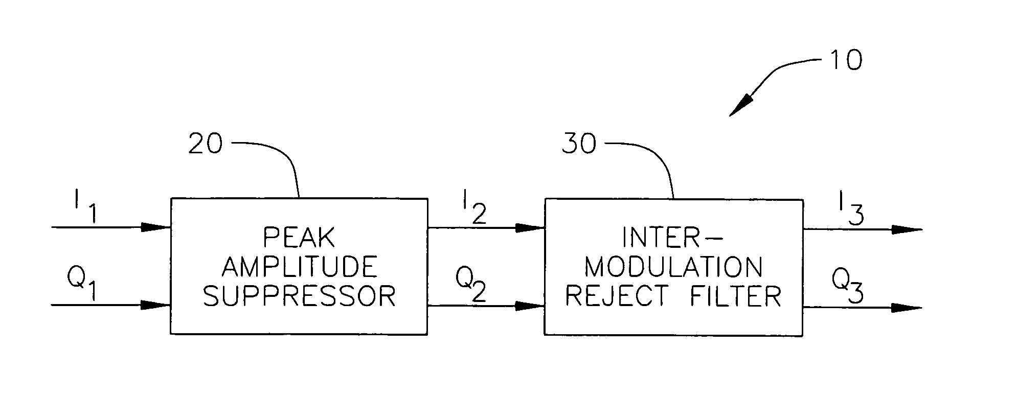
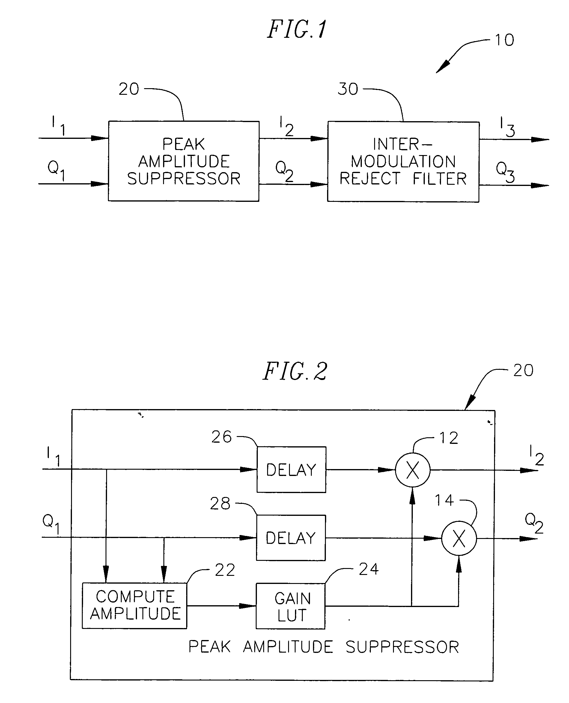
[0034]FIG. 1 is a simplified block diagram of an illustrative implementation of a system for crest factor reduction in accordance with the teachings of the present invention. The system 10 includes a peak amplitude suppressor 20 and an intermodulation rejection filter 30. A baseband, IF or RF input signal may be expressed as:

X1(n)=I1(n)+jQ1(n)  ...


PUM


Abstract

A crest reduction system and method. The inventive system includes a first circuit for suppressing peak amplitudes of an input signal and providing a peak amplitude suppressed signal in response thereto and a second circuit coupled to the first circuit for rejecting intermodulation distortion in the amplitude suppressed signal. In the illustrative implementation, the first circuit is a peak amplitude suppressor having circuitry for computing an amplitude of the input signal and for computing a gain factor for the input signal in response thereto. In the best mode, the gain factor is obtained from a lookup table. The peak amplitude suppressor further includes a multiplier for applying the gain factor to the input signal. In the illustrative embodiment, the second circuit includes a plurality of bandpass filters and a summer for combining the outputs thereof.

Description

CROSS-REFERENCE TO RELATED APPLICATION [0001] This application claims the benefit of U.S. Provisional Application No. 60 / 616,716, filed Oct. 7, 2004, the disclosure of which is incorporated herein by reference.BACKGROUND OF THE INVENTION [0002] 1. Field of the Invention [0003] The present invention relates to electrical and electronic circuits and systems. More specifically, the present invention relates to systems and methods for reducing crest factor in electrical and electronic circuits and systems. [0004] 2. Description of the Related Art [0005] In Multi-Carrier Power Amplifier (MCPA) communication transmission applications, multiple carriers are typically combined in the baseband, intermediate frequency (IF) or radio frequency (RF) frequency range and the resulting signal is transmitted using a single power amplifier. An objective for MCPA transmission is to transmit a signal at a very high efficiency while maintaining a low Adjacent Channel Power Ratio (ACPR) to meet spectral ...

Claims


Application Information

Patent Timeline
IPC IPC(8): H04L25/03
CPCH04L27/2624
Inventor CAI, KHIEM V.KENT, SAMUEL DAVIS IIIDEVENDORF, DON C.
Owner MICROELECTRONICS TECH INC
Why Eureka
Try Eureka