
Method and apparatus for red-eye detection in an acquired digital image

a technology of digital image and detection method, applied in image data processing, character and pattern recognition, instruments, etc., can solve the problems of deteriorating the overall detection of red eye defects, objectionable phenomena, etc., and achieve the reduction of false positives, low computing power requirements, and color misclassification of pixels and regions belonging to non-defect areas.

Active Publication Date: 2006-06-08
FOTONATION LTD
View PDF99 Cites 234 Cited by
  • Summary
  • Abstract
  • Description
  • Claims
  • Application Information

AI Technical Summary

Benefits of technology

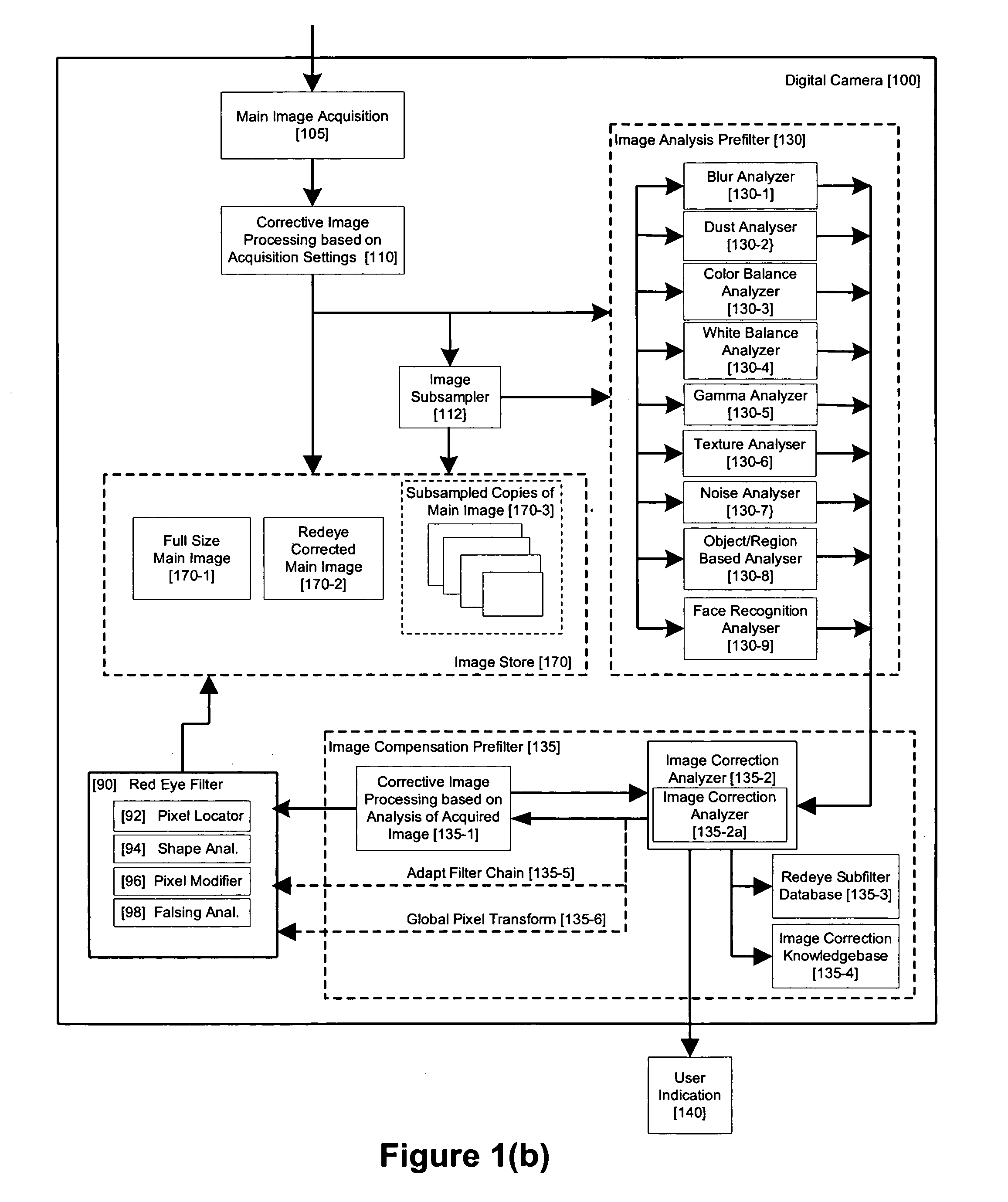
"The present invention provides a method and apparatus for detecting and correcting red-eye defects in acquired digital images. The invention compensates for sub-optimally acquired images that may affect the correct operation of red-eye detection by performing image analysis and applying corrective image processing based on the analysis prior to or in conjunction with applying one or many redeye detection filters to the acquired image. The invention optimizes the pre-filtering process by applying image transformations at the pixel level during the redeye detection process. The invention also improves the overall success rate and reduces the false positive rate of red-eye detection and reduction by compensating for non-optimally acquired images without requiring that corrective image processing be applied to the full resolution image. The invention can be implemented inside digital cameras as part of the post-acquisition processing step and has a low requirement for computing power and memory resources. The invention is not limited in its detection of red-eye defects by requirements for clearly defined skin regions matching a human face. The invention also allows for concatenation image quality transformations and red-eye detection to improve overall performance."

Problems solved by technology

This objectionable phenomenon is well understood to be caused in part by a small angle between the flash of the camera and the lens of the camera.
For example an image with suboptimal exposure may deteriorate the overall detection of red-eye defects.

Method used


Image

  • Method and apparatus for red-eye detection in an acquired digital image
  • Method and apparatus for red-eye detection in an acquired digital image
  • Method and apparatus for red-eye detection in an acquired digital image

Examples


Embodiment Construction

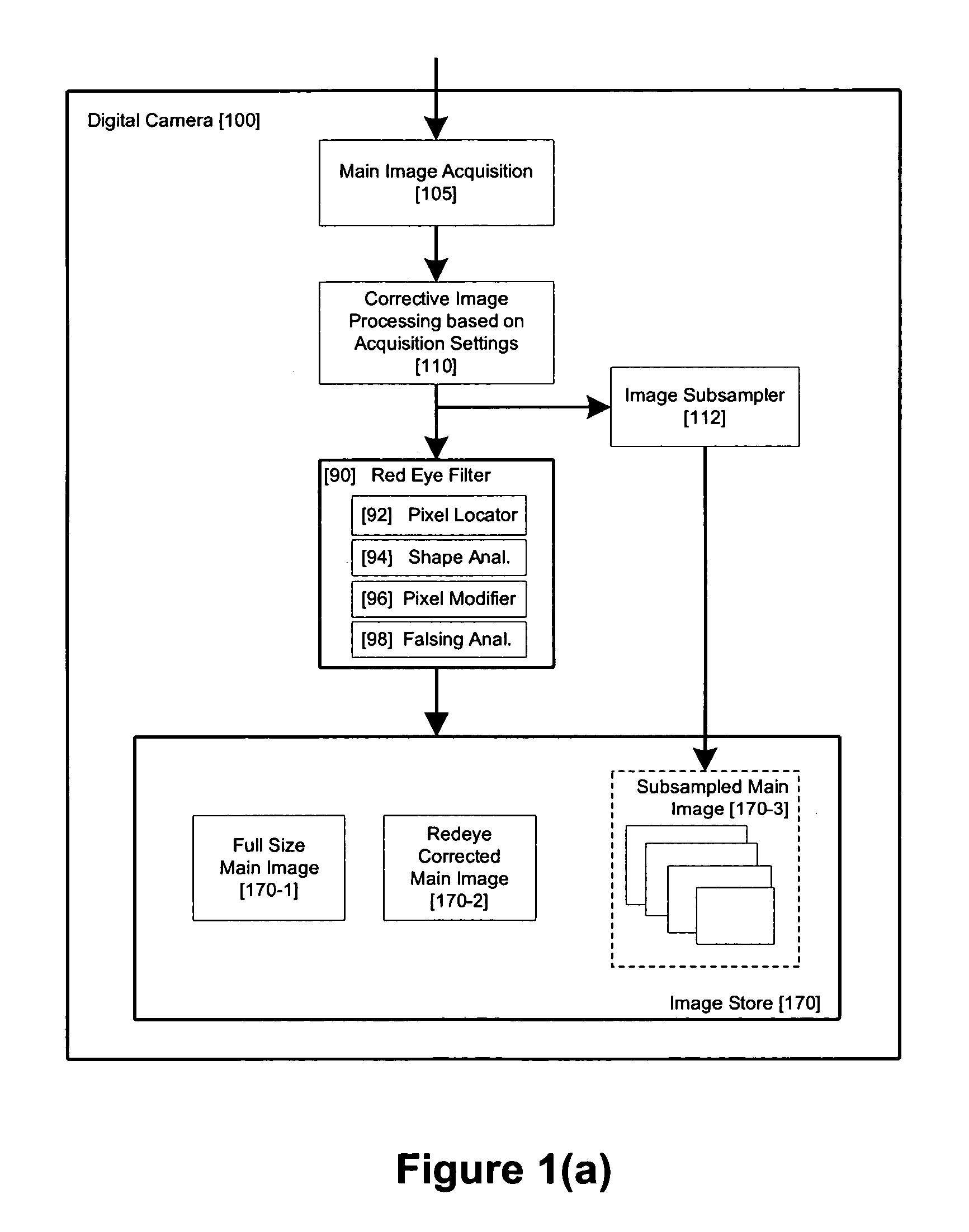
[0037]FIG. 1 illustrates a prior art in-camera redeye system. Within the camera 100 a main image is acquired 105 from a sensor subsystem. This image is further processed 110 based on image acquisition parameters such as ambient lighting, length of exposure, usage of pre-flash and flash, lens focal length & aperture settings, etc. This image processing is pre-calibrated during the design of the camera and, due to the non-linear relationships between the various acquisition parameters, it typically involves a significant amount of empirical testing using as broad a range of image capture conditions as is practical. Thus, even though modern digital cameras have much improved auto-focus and auto-exposure algorithms it is still possible to capture images of non-optimal quality either through incorrect camera settings or through encountering conditions which are not fully accounted for by the empirical calibrations process for that camera.

[0038] After this image processing is completed t...


PUM


Abstract

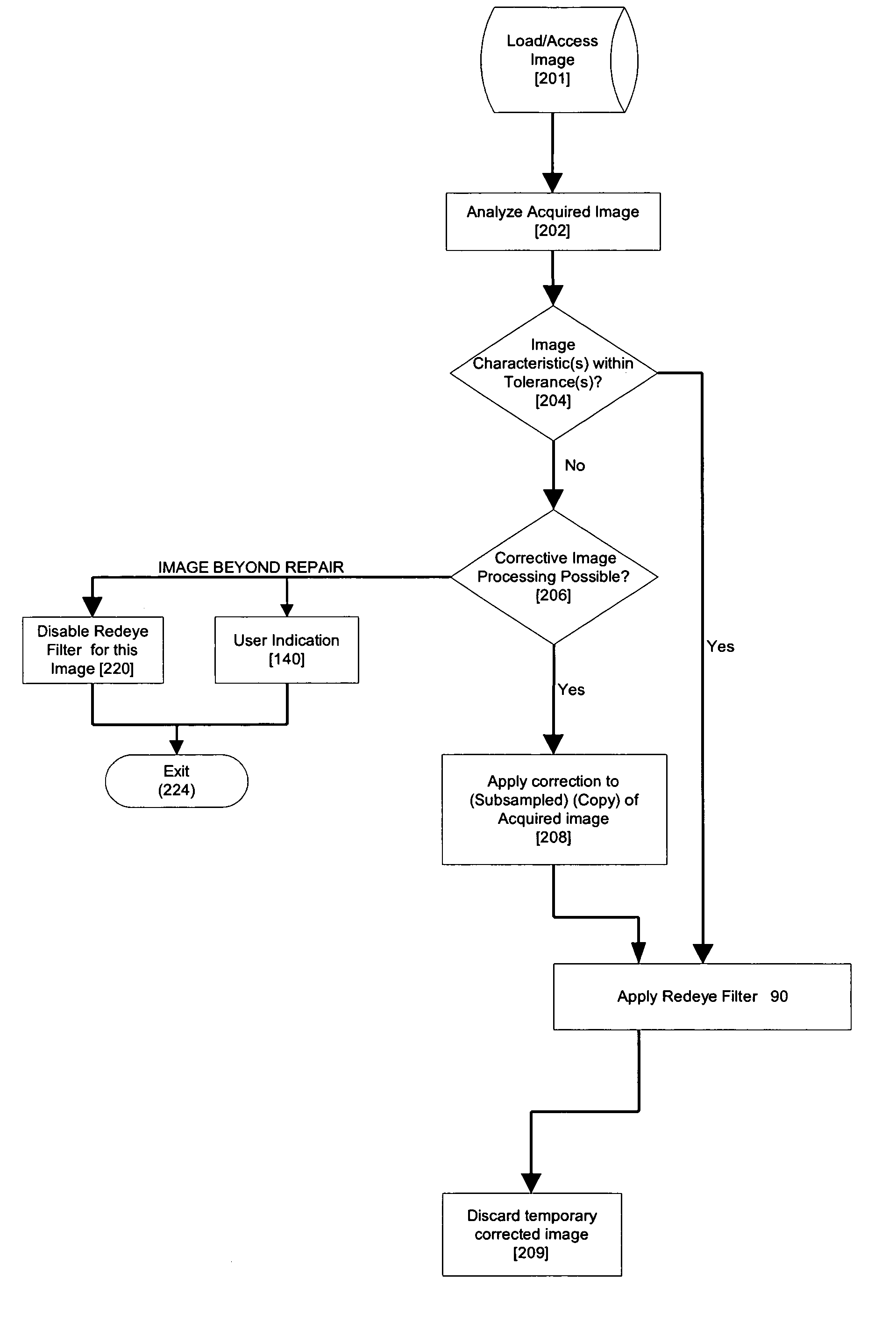
A method for red-eye detection in an acquired digital image comprises acquiring a first image and analyzing the first acquired image to provide a plurality of characteristics indicative of image quality. The process then determines if one or more corrective processes can be beneficially applied to the first acquired image according to the characteristics. Any such corrective processes are then applied to the first acquired image. Red-eye defects are then detected in a second acquired image using the corrected first acquired image. Defect detection can comprise applying a chain of one or more red-eye filters to the first acquired image. In this case, prior to the detecting step, it is determined if the red-eye filter chain can be adapted in accordance with the plurality of characteristics; and the red-eye filter is adapted accordingly.

Description

PRIORITY [0001] This application is a continuation-in-part (CIP) which claims the benefit of priority to U.S. patent application Ser. No. 11 / 182,718, filed Jul. 15, 2005, which is a CIP of U.S. application Ser. No. 11 / 123,971, filed May 6, 2005 and which is a CIP of U.S. application Ser. No. 10 / 976,336, filed Oct. 28, 2004, each of these application being hereby incorporated by reference.FIELD OF THE INVENTION [0002] The present invention relates to digital image processing, and more particularly to a method and apparatus for red-eye detection in an acquired digital image. BACKGROUND TO THE INVENTION [0003] Red-eye is a phenomenon in flash photography where a flash is reflected within a subjects eye and appears in a photograph as a red dot where the black pupil of the subject's eye would normally appear. The unnatural glowing red of an eye is due to internal reflections from the vascular membrane behind the retina, which is rich in blood vessels. This objectionable phenomenon is wel...

Claims


Application Information

Patent Timeline
Patent Type & Authority Applications(United States)
IPC IPC(8): G06K9/00G06K9/40
CPCG06K9/0061G06T5/008G06T2207/20008G06T2207/30216G06V40/193G06T5/94
Inventor STEINBERG, ERANPRILUTSKY, YURYBIGIOI, PETRONELNANU, FLORIN
Owner FOTONATION LTD
Learn More