Chamfering air tool

a technology of air tool and chamfering angle, which is applied in the direction of manufacturing tools, woodworking safety devices, transportation and packaging, etc., can solve the problems of inefficient work, difficult to apply uniform force, and long time taken for work, so as to improve abrasion resistance, eliminate cut chips, and improve the effect of shap

Inactive Publication Date: 2006-06-08
CHOI CHEOL HWAN
View PDF18 Cites 22 Cited by
  • Summary
  • Abstract
  • Description
  • Claims
  • Application Information

AI Technical Summary

Benefits of technology

[0011] Therefore, it is an object of the present invention to provide a chamfering air tool in which a cutter has an improved shape to always form chamfering portions with the same shape, a guide flange for guiding an air tool in surface contact with a subject to be processed so that the cutter may chamfer the subject in exact contact, the air giving a driving force to improve abrasion resistance and eliminate cut chips is partially flowed near to the c

Problems solved by technology

In this work, it is not easy to apply a uniform force, and the subject is not chamfered regularly, particularly for a round, since an interface between the subject and the chamfering air tool is not regular due to wrong posture of the worker.
That is to say, since a worker chamfers an edge of the subject with the use of the cutter by eye measure, a chamfering angle is not regular and much time is taken for the work, inefficiently.
In addition, in the work using the conventional cutter, the subject and the cutter may be heated due to friction between them, so a worker may get burned.
Moreover, if the cutter is heated, abrasion resistance of the cutter is deteriorated, so the cutter should be exchanged very frequently.
Furthermore, cut chips of the subject that is cut by the cutter are not easily discharged, thereby disturbing the cooling process or the chamfering work.
However, a

Method used


Image

  • Chamfering air tool
  • Chamfering air tool
  • Chamfering air tool

Examples


Embodiment Construction

[0021] Hereinafter, the present invention will be described in more detail referring to the drawings.

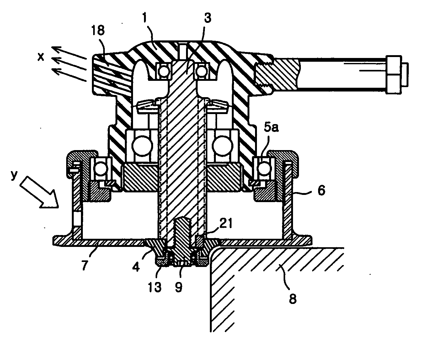
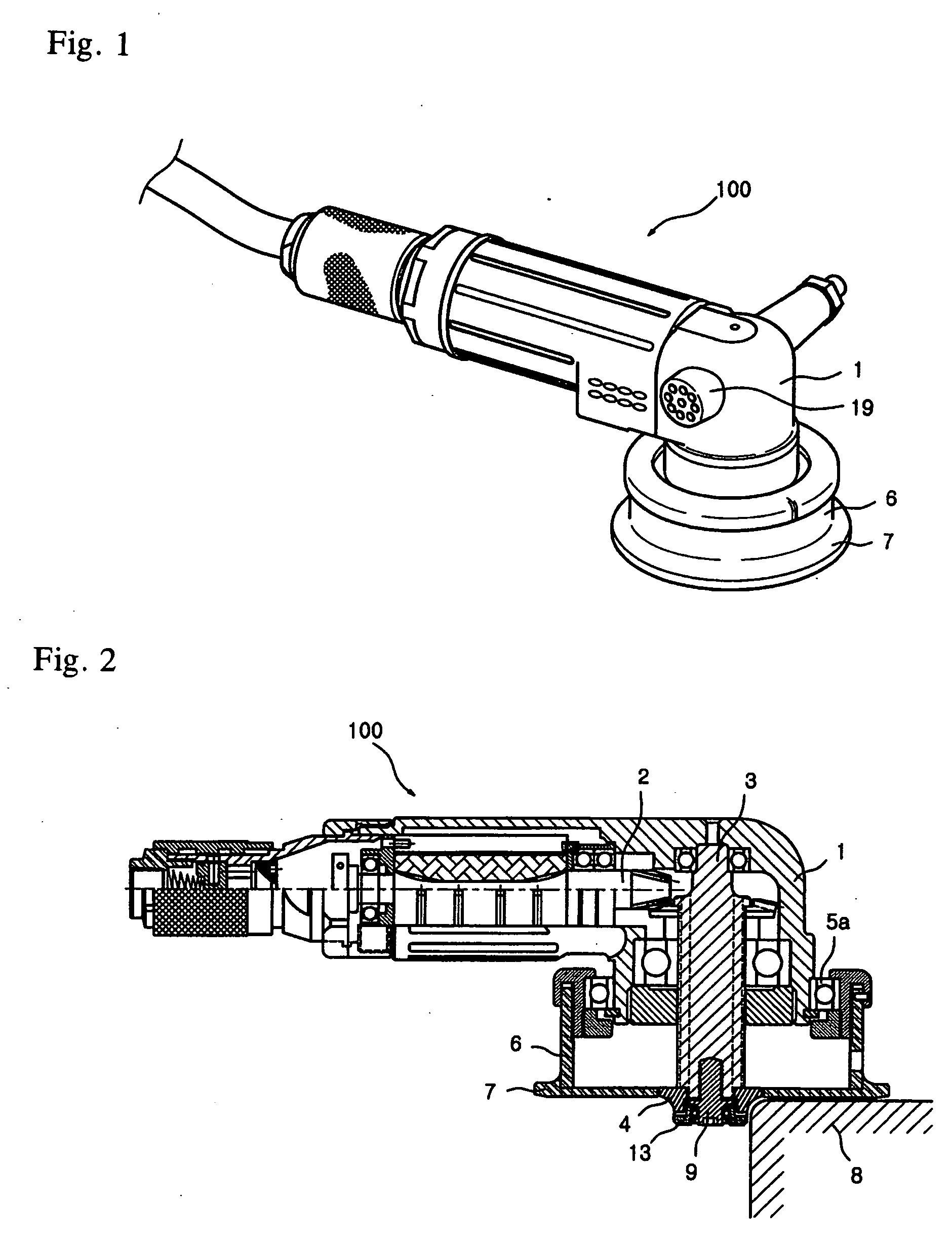
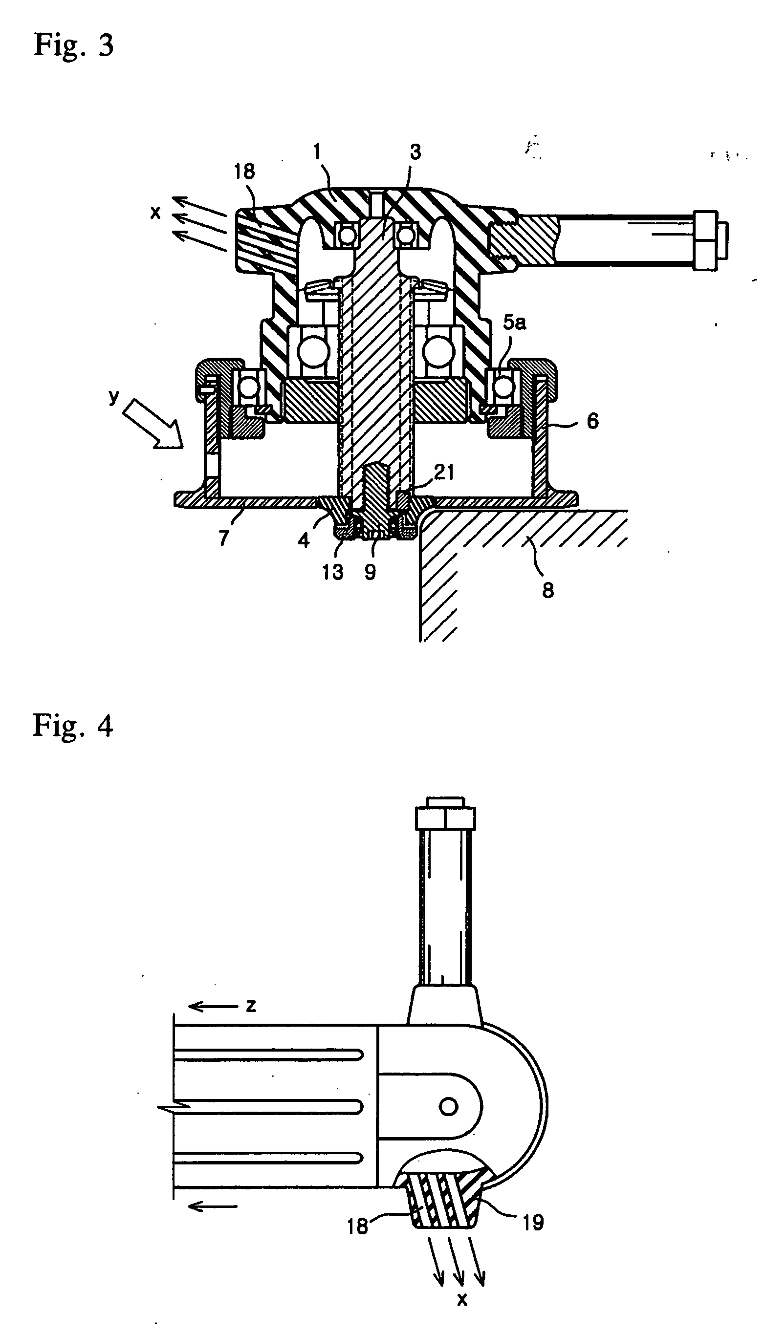
[0022] A chamfering air tool 100 of the present invention includes a driving shaft 2 rotated by means of air pressure in a casing 1, a rotary shaft 3 perpendicularly combined to the driving shaft 2 so as to be rotated, and a cutter 4 fixed to an end of the rotary shaft 3 by means of a fixing bolt 9. A bearing 5a is mounted to the casing 1 on which the rotary shaft 3 is protruded. An upper end of a cylindrical rotational cap 6 having a length corresponding to a protruded length of the rotary shaft 3 is mounted to an outer circumference of the bearing 5a. In addition, a guide flange 7 having a disk shape is mounted to a lower end of the rotational cap 6 so that the guide flange 7 is rotatable by means of the bearing 5a in contact with a subject 8 to be processed. Of course, the guide flange 7 has a ring shape with a hollow center, and the cutter 4 for chamfering is positioned in the c...


PUM

PropertyMeasurementUnit
Lengthaaaaaaaaaa
Forceaaaaaaaaaa
Pressureaaaaaaaaaa

Abstract

A chamfering air tool includes a driving shaft rotated by air pressure in a casing, a rotary shaft perpendicularly combined to the driving shaft for rotation, and a cutter fixed to the rotary shaft. Air holes are formed through the rotary shaft in a length direction. Air discharge groove is formed in the cutter. Air hole communicated with the air hole is formed in the fixing bolt head. Air path is formed in the fixing bolt head to keep a predetermined gap from the cutter. Guide ring having a diameter approximate to a lower end of the cutter is rotatably mounted to the fixing bolt head. Thus, air is blown to air hole of the rotary shaft, air hole formed in the fixing bolt head, air path formed between the cutter and the guide ring, and air discharge groove of the cutter, thereby eliminating cut chips and cooling the cutter.

Description

BACKGROUND OF THE INVENTION [0001] 1. Field of the Invention [0002] The present invention relates to a chamfering air tool for rounding an edge of a subject with softly moving in surface contact with the edge of the subject, and more particularly to a chamfering air tool in which a rotating cutter having a shape suitable for chamfering is mounted to a rotary shaft having an air hole, a rotational cap having a guide flange for guiding an air tool in surface contact with a subject is installed to a casing, and an air discharge hole is formed to be inclined to discharge air in a direction approximately opposite to a resultant of a force for advancing the air tool and a force for cutting the subject, whereby the guide flange and the rotating cutter shapes a chamfering portion uniformly and stably, the air blown to the air hole discharges out cut chips and dusts and cools down to improve efficiency of work, and the air tool is more closely adhered to the subject and easily advanced by me...

Claims


Application Information

Patent Timeline
IPC IPC(8): B23C1/20
CPCB23B31/4073B23C3/126B23C5/12B23C5/28B23C2210/70Y10T409/30392Y10T409/308456Y10T409/303976Y10T409/306496Y10T408/455Y10T409/304032Y10T409/304144Y10T409/304088
Inventor CHOI, CHEOL-HWAN
Owner CHOI CHEOL HWAN
Why Eureka
Try Eureka