
Color filter having nanoparticles for liquid crystal display

Inactive Publication Date: 2006-06-08
INNOLUX CORP
View PDF3 Cites 86 Cited by
  • Summary
  • Abstract
  • Description
  • Claims
  • Application Information

AI Technical Summary

Benefits of technology

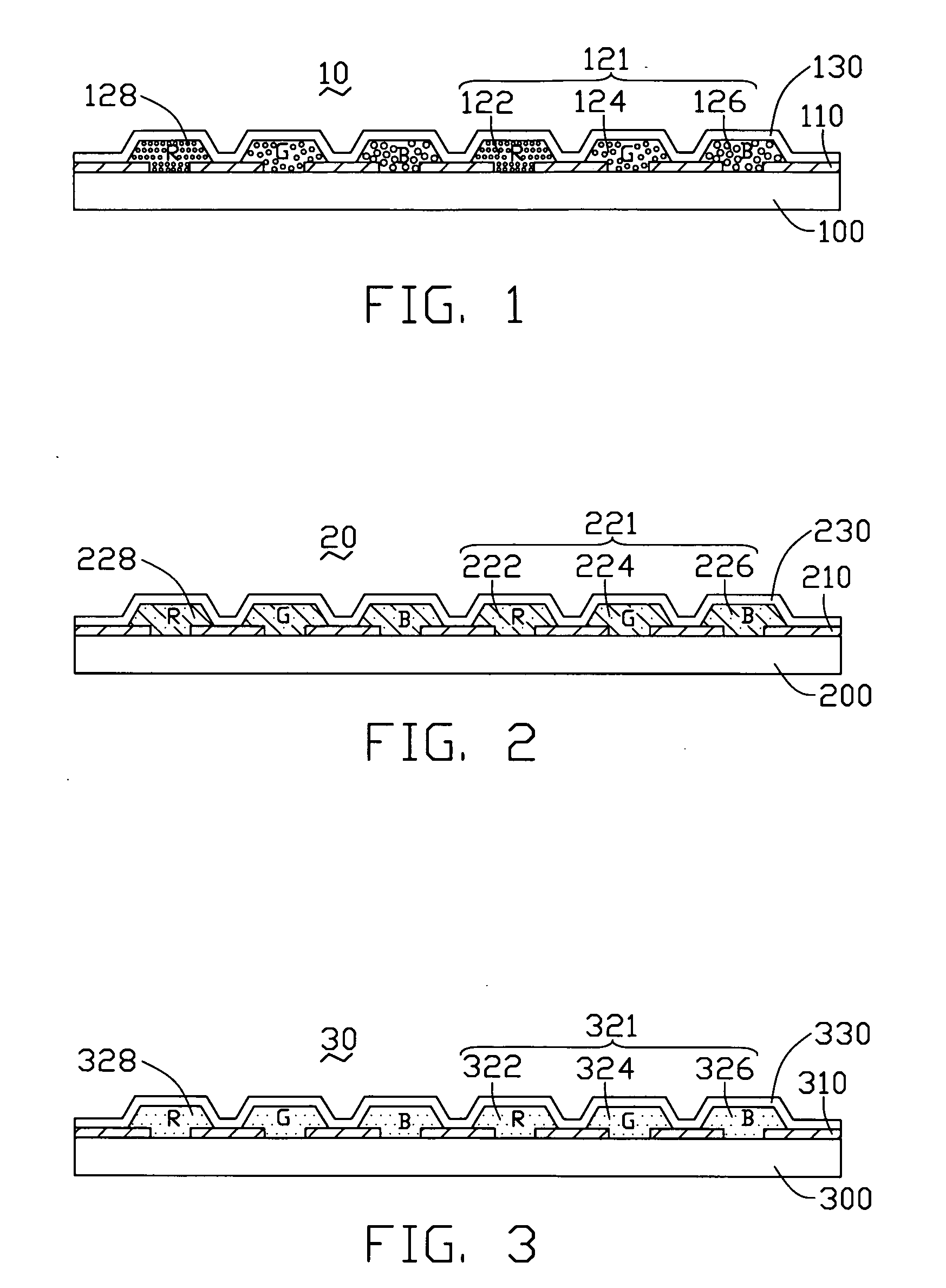
[0008] The material of the nanoparticles can be metal, a semiconductor, and / or a semiconductor compound. Light transmission of the color filter can be controlled by configuring diameters and shapes of the nanoparticles accordingly. The color filter performs with high thermal resistance, high light transmission, and good contrast.

Problems solved by technology

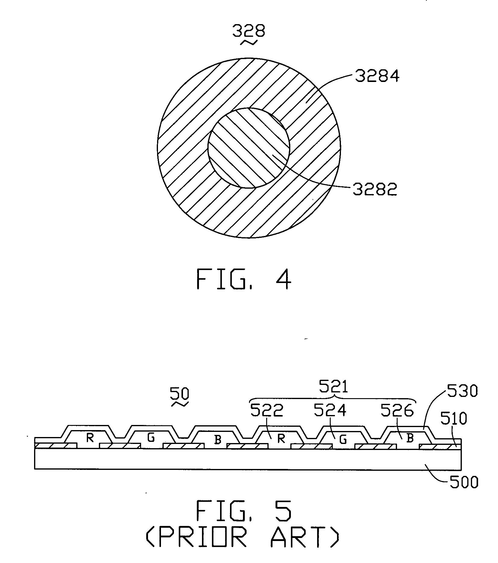
However, the thermal resistance of the pigment is generally poor, which results in poor color reproduction of the color filter 50.

Method used


Image

  • Color filter having nanoparticles for liquid crystal display
  • Color filter having nanoparticles for liquid crystal display
  • Color filter having nanoparticles for liquid crystal display

Examples


Embodiment Construction

[0016] Reference will now be made to the drawings to describe the preferred embodiments in detail.

[0017]FIG. 1 is a schematic, side cross-sectional view of part of a color filter of the first preferred embodiment of the present invention. The color filter 10 includes a substrate 100, a black matrix 110 disposed on the substrate 100, and a patterned photo-resist layer (not labeled) disposed in and around the black matrix 110. A transparent overcoat layer 130 is arranged on and covers the black matrix 110 and the photo-resist layer. The substrate 100 functions as a carrier of the above-described elements. The photo-resist layer includes a plurality of pixels 121. Each pixel 121 includes three sub-pixels: a red sub-pixel 122, a green sub-pixel 124, and a blue sub-pixel 126, all of which are arranged in a predetermined pattern. The black matrix 110 is disposed in and around the sub-pixels 122, 124 and 126, for preventing light rays from mixing among adjacent sub-pixels 122, 124 and 126...


PUM


Abstract

An exemplary color filter (10) for a liquid crystal display includes a substrate (100), a black matrix (110), and a photo-resist layer. The photo-resist layer defines a plurality of pixels (121). Each pixel includes a red sub-pixel (122), a green sub-pixel (124), and a blue sub-pixel (126). Each sub-pixel includes a plurality of nanoparticles (128). The black matrix is disposed in and around the sub-pixels. A material of the nanoparticles can be metal, alloy, a semiconductor, and / or a semiconductor compound. Light transmission of the exemplary color filter can be controlled by configuring the materials, diameters, and shapes of the nanoparticles accordingly. The color filter performs with high thermal resistance, high light transmission, and good contrast. In other embodiments, fluorescence of a color filter can also be controlled by configuring the materials, the diameters, and the shapes of the nanoparticles accordingly.

Description

FIELD OF THE INVENTION [0001] The present invention relates to color filters, and more particularly to a color filter for a liquid crystal display (LCD) device. GENERAL BACKGROUND [0002] Liquid crystal displays are commonly used as display devices for compact electronic apparatuses, because they are not only very thin but also provide good quality images with little power consumption. [0003] A typical LCD device includes an LCD panel. The LCD panel includes two transparent substrates parallel to each other, and a liquid crystal layer disposed between the two substrates. In order to make the liquid crystal display device display a full-colored image, a color filter is usually employed in the device at one of the substrates. A typical color filter provides three primary colors: red, green, and blue (RGB). The color filter, the liquid crystal layer, and a switching element arranged on the substrate cooperate to make the liquid crystal display device display full-colored images. [0004] ...

Claims


Application Information

Patent Timeline
IPC IPC(8): G02F1/1335G02B5/20
CPCG02B5/206G02F1/133516
Inventor WU, MEI LING
Owner INNOLUX CORP
Learn More