Cover layer with high thermal resistance and high reflectivity for a printed circuit board

Inactive Publication Date: 2015-09-10
TAIFLEX SCI
View PDF11 Cites 4 Cited by
  • Summary
  • Abstract
  • Description
  • Claims
  • Application Information

AI Technical Summary

Benefits of technology

The present invention provides a cover layer with high thermal resistance and high reflectivity for printed circuit boards. The cover layer does not yellow under surface mount technology process and maintains high reflectivity. The cover layer also has better structural strength, not prone to cracking. The cover layer raises the reflectivity of the printed circuit board and reduces the absorption of light, enhancing the luminous efficacy and color rendering index of the electronic product without raising luminous intensity. The cover layer is thin and can be applied to compact products that are thin or slim. The cover layer comprises a releasing layer and is applicable to both rigid and flexible printed circuit boards.

Problems solved by technology

As light of illumination elements of the illumination module passes through the secondary optical elements, loss of light, such as light absorption and light scattering, may occur, and hence light of the illumination module is not effectively utilized.
Also, luminous efficacy and color rendering index of the electronic product is affected.
For example, using light guiding plates can achieve a homogenized planar light source effect of a back light module, but light absorption and light scattering of the light guide plate results in light loss.

Method used


Image

  • Cover layer with high thermal resistance and high reflectivity for a printed circuit board
  • Cover layer with high thermal resistance and high reflectivity for a printed circuit board
  • Cover layer with high thermal resistance and high reflectivity for a printed circuit board

Examples


embodiment 1

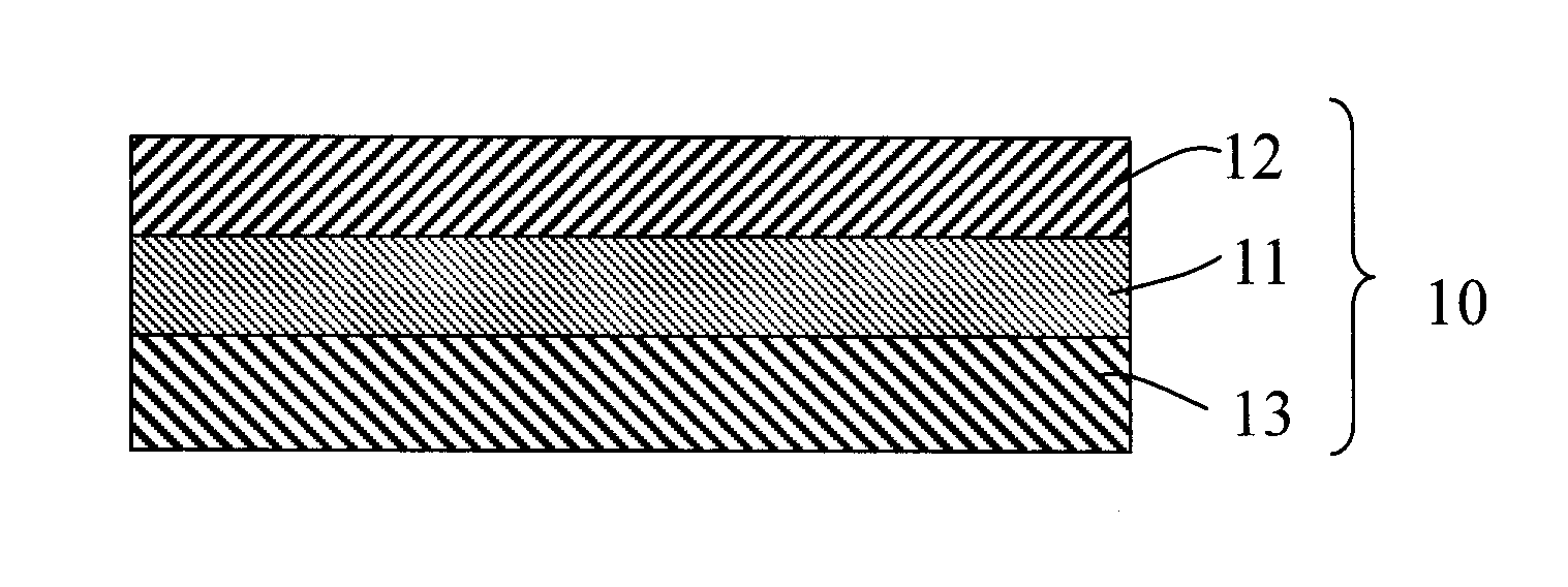
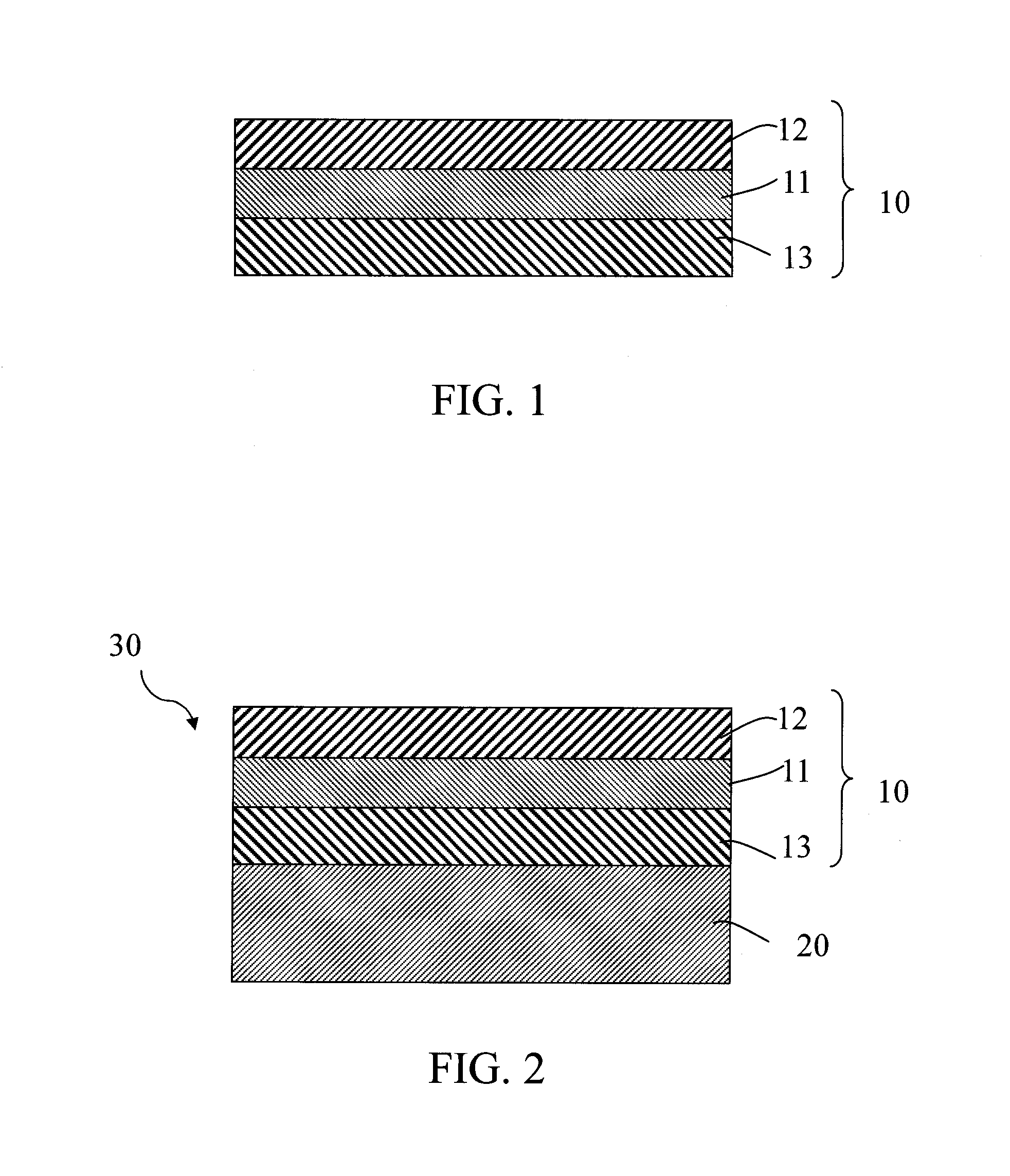
[0041]With reference to FIG. 1, a cover layer 10 with high thermal resistance and high reflectivity of a printed circuit board of the present embodiment comprised a polymer film 11, a reflective composite layer 12, an adhesive layer 13 and a releasing layer. The polymer film 11 had two side surfaces opposite to each other. The reflective composite layer 12 and the adhesive layer 13 were respectively mounted on the two side surfaces of the polymer film 11. The releasing layer was mounted on a side surface of the adhesive layer 13 that was opposite to the polymer film 11.

[0042]A method for making the cover layer 10 with high thermal resistance and high reflectivity for a printed circuit board of the present embodiment was as follows.

[0043]Firstly, the polymer film was provided.

[0044]Secondly, a first resin having functional groups, a first curing agent and a catalyst were mixed to from a first mixed solution. A first reflective pigment was dispersed in the first mixed solution by phys...

embodiment 2

[0050]The present embodiment was similar to Embodiment 1. The differences between the present embodiment and Embodiment 1 was that the content of the titanium dioxide powder was 30 vol. % based on the volume of the reflective composite layer. The reflectivity measurement result of the present embodiment was shown in Table 1.

embodiment 3

[0051]The present embodiment was similar to Embodiment 1. The differences between the present embodiment and Embodiment 1 was that the content of the titanium dioxide powder was 60 vol. % based on the volume of the reflective composite layer. The reflectivity measurement result of the present embodiment was shown in Table 1.

TABLE 1Measurement results of Embodiments 1 to 3.Embodiment123Thickness of reflective composite 20 μm20 μm20 μmlayerThickness tolerance of reflective ±2 μm±2 μm±2 μmcomposite layerKind of polymer filmPolyimidePolyimidePolyimideThickness of polymer film12.5 μm12.5 μm12.5 μmThickness of adhesive layer25 μm25 μm25 μmContent of first reflective pigment 20 vol %30 vol %60 vol %based on the volume of reflective composite layerReflectivity of cover layer (at a 89.0%90.2%90.5%wavelength of 550 nm)


PUM


Abstract

A cover layer of a printed circuit board has a polymer film, a reflective composite layer and an adhesive layer. The polymer film has a melting point greater than 260° C. The reflective composite layer is mounted on one side surface of the polymer film and has a first reflective pigment. The adhesive layer is mounted on another side surface of the polymer film. Also, at a range of wavelength where a reflectivity of the cover layer is greater than 89%, absorption of the polymer film to the same range of wavelength is less than 35%. The cover layer is laminated on a printed circuit board and after surface mount technology process at a temperature ranging from 160° C. to 320° C., the cover layer has a reflectivity over 89% without yellowing and delamination.

Description

BACKGROUND OF THE INVENTION[0001]1. Field of the Invention[0002]The present invention relates to a cover layer for a printed circuit board; particularly, to a cover layer with high thermal resistance and high reflectivity for a printed circuit board.[0003]2. Description of the Prior Art(s)[0004]Light transmission and light distribution effect of an illumination module of an electronic product are achieved by using secondary optical elements. As light of illumination elements of the illumination module passes through the secondary optical elements, loss of light, such as light absorption and light scattering, may occur, and hence light of the illumination module is not effectively utilized. Also, luminous efficacy and color rendering index of the electronic product is affected. In addition, after light of the illumination elements of the illumination module passes through the secondary optical elements, luminous intensity of illumination elements decays with distance; thus, raising p...

Claims


Application Information

Patent Timeline
IPC IPC(8): H05K5/03
CPCH05K5/03H05K1/0209H05K1/0274H05K3/281H05K2201/0195H05K2201/2054Y10T428/24959
Inventor HUNG, TZU-CHINGSHIH, YU-CHENTIEN, FENG-JUNGLU, CHEN-KUOLEE, YU-HSIENWU, SU-PING
Owner TAIFLEX SCI
Why Eureka
Try Eureka