[0006]Attachment joints of the thermal
protection system panels to the
substructure (metallic skin of the vehicle) are often bolted, though this approach cannot be used in the sections with a difficult access from within the vehicle. An alternative method based on integral tendons and mortises which enable the external replacement of fasteners is disclosed by Riedell (U.S. Pat. No. 6,827,312). Another attachment method is disclosed by Riccitiello, et al (U.S. Pat. No. 4,713,275) which employs bolted tabs or clips located on the side of the insulation tiles or shells. An
advantage of the present invention over Riccitiello is that the outer thermal
protective shield is firmly attached directly to the
space vehicle's outer metallic skin with fasteners such as hex nuts which serves to support the inner tile shield which in Riccitiello is attached only with an
adhesive material. A further
advantage of the present invention over that disclosed in Riccitiello is the greater ease of replacing the outer shield tiles. The outer
protective shield tiles must necessarily be assembled very close together. Riccitiello requires access to the sides of the inner tile shield in order to attach the outer tile shield. The present invention does not require access to the sides of the inner tile shield because the attachment rods pass perpendicularly through the inner tile shield and outer metallic skin of the
spacecraft. Additionally, in order to remove a damaged outer tile shield, the present invention requires a
technician to simple remove the inner fasteners such as hex nuts which releases the outer tile shield. Thus, a damaged outer tile shield may be readily replaced without affecting adjacent protective tiles.
[0007]The present invention comprises a thermal protection system for space and hypersonic vehicles capable of withstanding
high velocity impact during
takeoff and reentry into the
atmosphere (space vehicles) and during hypersonic flight (hypersonic vehicles) without immediate failure. As a result of this impact
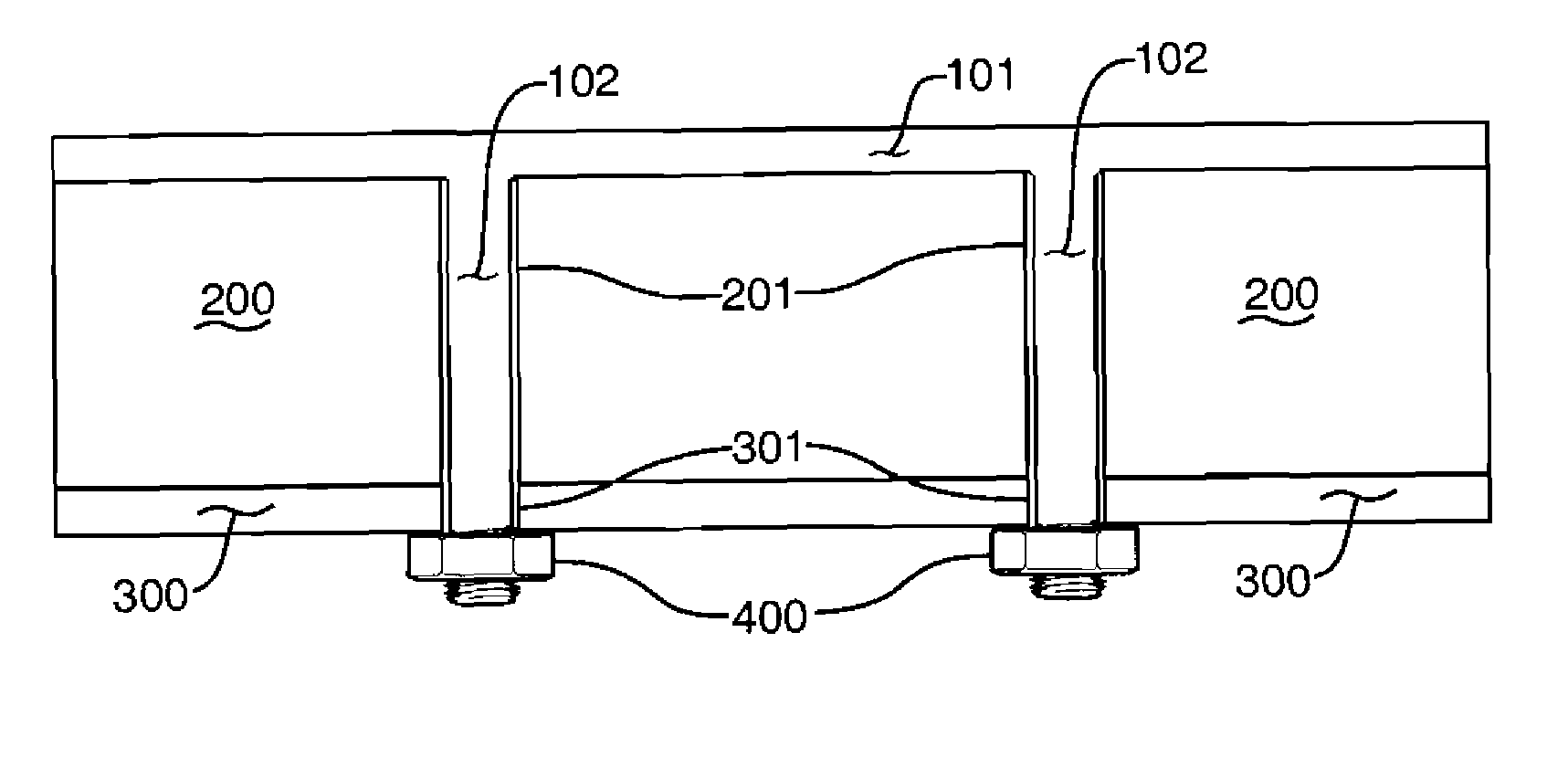
survivability, the vehicle would survive the flight and the necessary repairs can be made upon its safe return. The thermal protection system can also survive low velocity impact when the vehicle is on the ground, while still protecting the main thermal protection element. The design is based on dividing the thermal protection system into two components pressed against each other by fasteners but without a continuous material connection along the interface. Accordingly, impact-generated cracks in the outer shield (
ceramic matrix composite panel) stop at the surface of this shield adjacent to the internal component (ceramic tile) and do not propagate into this component that serves as a major heat protection element. This ensures that even if the outer shield is damaged, a
catastrophic failure such as occurred in
Space Shuttle Columbia would not occur in the present design. The other
advantage of this invention is an easy access to a damaged external shield of a thermal protection system for its quick replacement.
[0008]It is therefore an object of the present invention to provide a discontinuous thermal protection system with the outer
ceramic matrix composite CMC shield capable of both withstanding external impacts (with or without
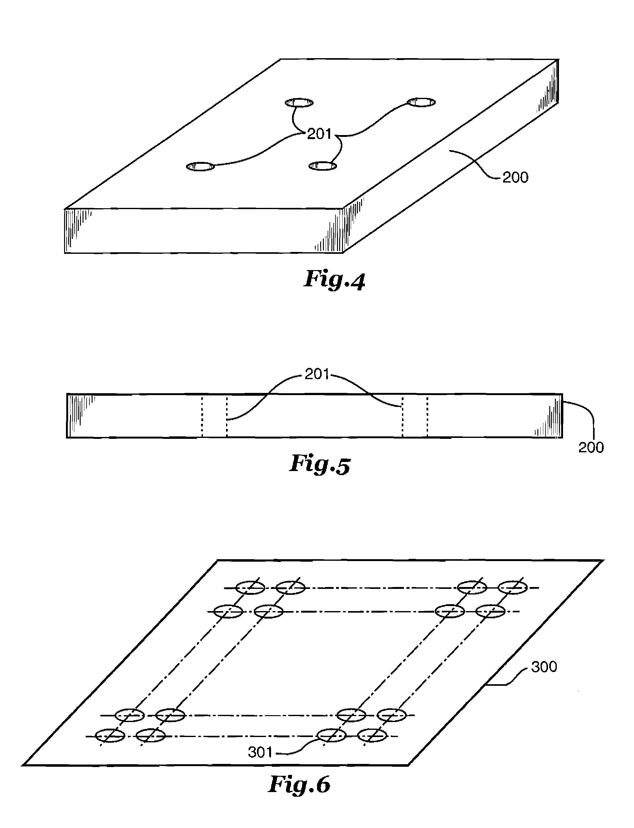
cracking) as well as surviving flight thermal loads and the inner ceramic the capable of withstanding prescribed thermal loads for a prescribed time interval without conducting a dangerous amount of heat to the main structure (skin) of the vehicle.
Ceramic matrix fasteners connecting the thermal protection system to the main structure have high
thermal resistance, i.e. they can withstand the same temperature as the CMC shield and ceramic the of a thermal protection system. These fasteners consist of ceramic fibers embedded in a ceramic matrix, providing them with sufficient strength and stiffness to guarantee a safe
assembly.
[0009]It is another object of this invention to provide for a simple method of disassembly of two components of thermal protection system, namely the outer shield and the inner tile separating them from the main structure (metallic skin) of the vehicle.
[0010]It is another object of this invention to provide for a reliable attachment of the ceramic tile to the structure (metallic skin) of the air vehicle during the flight through the fasteners pressing the outer shield to the tile and furthermore, pressing the tile to the skin of the air vehicle avoiding its detachment during the flight.
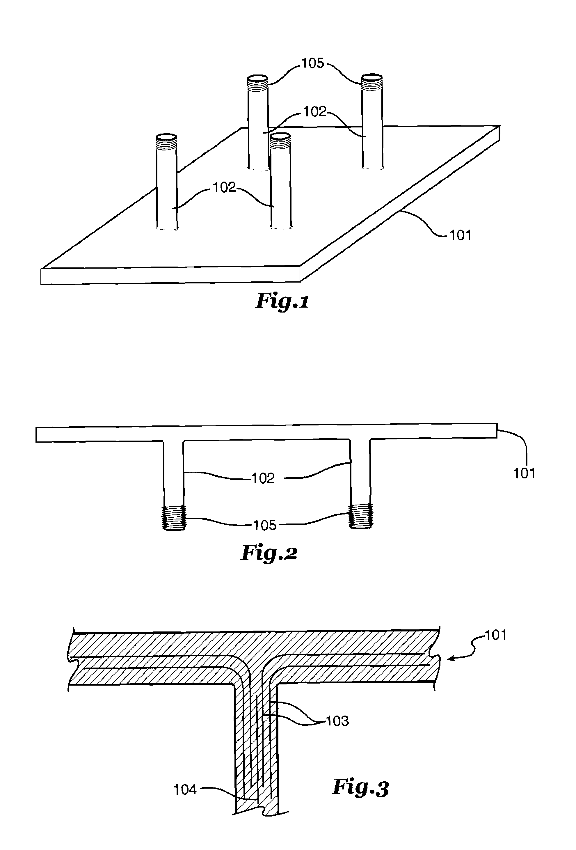
[0011]It is another object of this invention to provide a design of the outer shield incorporating the fasteners used to join the shield and the inner ceramic tile to the structure (skin) of the vehicle. The fasteners being manufactured together with the outer shield, the integrity of the design is preserved.

