
Handover method and base station control apparatus

a control method and control apparatus technology, applied in the direction of electrical equipment, network planning, selection arrangements, etc., can solve the problems of unsuitable re-selection of radio resources, loss of calls, and inability to secure a usable communication band, so as to improve communication speed and facilitate the effect of processing load and high real-time servi

Inactive Publication Date: 2006-06-08
FUJITSU LTD
View PDF2 Cites 59 Cited by
  • Summary
  • Abstract
  • Description
  • Claims
  • Application Information

AI Technical Summary

Benefits of technology

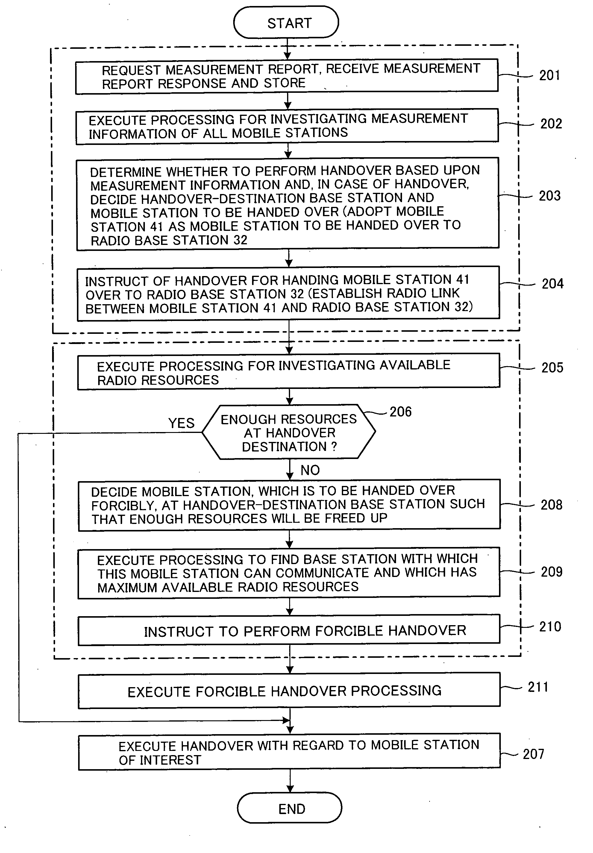
[0020] Accordingly, an object of the present invention is to enable handover reliably and prevent a situation in which re-selection of radio resources and suspension of handover ascribable to handover failure is prevented.
[0021] Another an object of the present invention is to make it possible to perform handover reliably by exercising handover control that takes into account the status of use and availability of radio resources at a radio base station that is the destination of handover.
[0022] A further object of the present invention is to vary the timing of handover decision processing in accordance with communication service, communication speed and traveling speed, whereby handover can be performed efficiently and reliably without delay.

Problems solved by technology

In the prior art, therefore, a problem which arises is that the radio resources of the radio base station that is the handover destination may be inadequate, making it impossible to secure a usable communication band.
However, if the same amount of radio resources cannot be secured or if the electric field strength of the newly set-up radio channel is not suited to communication, radio resources are selected again or handover is suspended.
The re-selection of radio resources is undesirable in that a long period of time is required until handover is completed, and suspending handover invites loss of calls.
Further, even if communication per se can be continued, a major decline in throughput is invited and there is the danger that users will be inconvenienced.
However, this example of the prior art is not related to handover control initiated by roaming and does not hand over mobile stations that are unrelated to degree of priority.

Method used


Image

  • Handover method and base station control apparatus
  • Handover method and base station control apparatus
  • Handover method and base station control apparatus

Examples


first embodiment

(A) First Embodiment

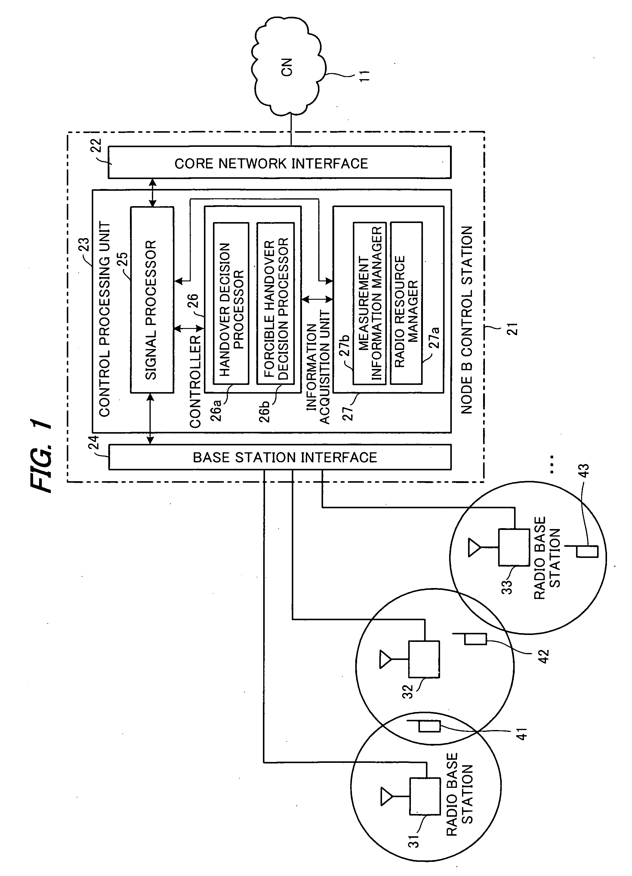
[0044]FIG. 1 is a diagram illustrating the configuration of a wireless communication system according to the present invention. The system comprises nodes of four types, namely a core network 11, a Node B control station 21, radio base stations 31, 32, 33, . . . and mobile stations 41, 42, 43, . . . .

[0045] (1) Node B Control Station

[0046] The Node B control station 21 has a core network interface 22, a control processing unit 23 and a base station interface 24. The core network interface 22 receives user data and the like from the core network 11 and sends it to a signal processor 25 of the control processing unit 23.

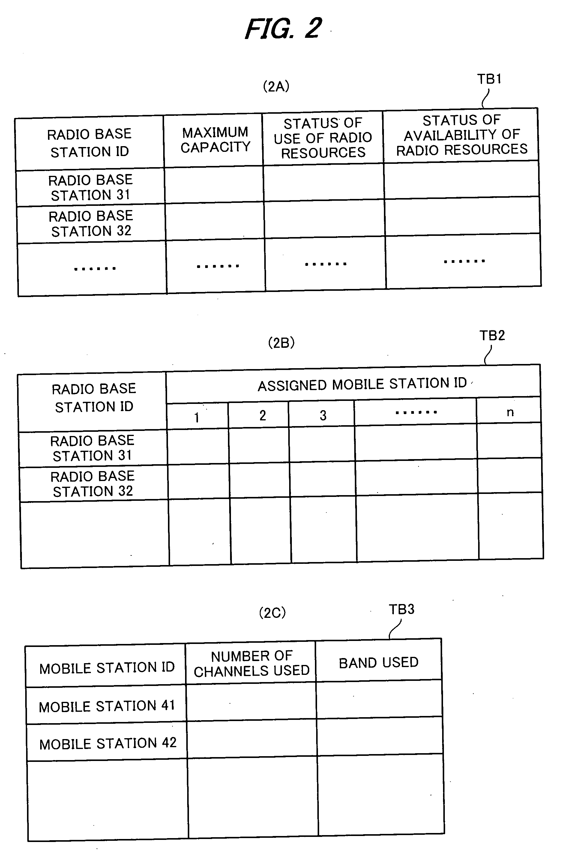
[0047] The signal processor 25 transmits the user data from the core network interface 22 and control signals (a terminal-to-control-station control signal and a base-station-to-control-station control signal), which enter from a controller 26, via the base station interface 24. The “terminal-to-control-station control signal” refers to a control...

second embodiment

(B) Second Embodiment

[0095] In the case of real-time communication (moving picture and voice services), it is required that momentary-interruption time be made as short as possible. Further, in high-speed data communication, handover requires enough time for preparation in order that many radio resources (many mobile stations) within the handover-destination base station may be forcibly handed over. Further, in case of high-speed roaming, handover occurs frequency owing to roaming. This makes it more likely that the required radio resources will not be obtainable. Accordingly, in case of real-time communication, high-speed data communication and communication at the time of high-speed roaming, it is necessary to hasten the handover execution timing of the first embodiment.

[0096] In order to hasten handover execution timing, it will suffice to lower a handover-start decision threshold value. In FIG. 8, (A) and (B) are diagrams for describing the relationship between handover executi...

third embodiment

(C) Third Embodiment

[0107] A third embodiment is an embodiment that obtains the handover-decision threshold value from a function dependent upon a combination of communication service, communication speed and traveling speed. This embodiment decides the timing of handover decision processing based upon the decision threshold value found.

[0108] In a wireless communication system having a base station and a plurality of mobile stations, a handover-decision threshold value Thi of a mobile station i is found as follows:

Thi=FuncAi[Th, real-time degree, required communication speed, traveling speed]  (1)

FuncAi[ ]=function dependent on real-time degree, required communication speed and traveling speed  (2)

[0109] Although FuncAi[ ] is not specifically stipulated, it can be expressed as the following function:

FuncAi[Th, real-time degree, required communication speed, traveling speed]=Th+f[real-time degree]+g[required communication speed]+h[traveling speed]  (3)

[0110] In the above equat...


PUM


Abstract

When handover control is performed in a wireless communication system in which a plurality of base stations and a plurality of mobile stations communicate wirelessly, the necessary radio resources are secured beforehand in a handover-destination radio base station before handover is performed, and handover is executed thereafter. In order to secure the radio resources, one or more mobile stations that are already communicating via the handover-destination base station are forcibly handed over to another radio base station, whereby the radio resources of the handover-destination radio base station are secured. This is followed by executing handover.

Description

BACKGROUND OF THE INVENTION [0001] This invention relates to a handover control method and base station control apparatus. More particularly, the invention relates to a handover control method in a wireless communication system, which has a plurality of base stations and a base station control apparatus that controls the plurality of base stations, for performing communication wirelessly between the base stations and a mobile station, and to the base station control apparatus. [0002] The commercialization of CDMA (Code Division Multiple Access) communication systems is proceeding at a rapid pace. Commercial service for wideband CDMA (W-CDMA) systems, which are for exchanging not only voice and still pictures that form the principal service at the present time but also large quantities of data such as moving pictures, also has begun. The specifications for these have been set by the 3GPP (3rd Generation Partnership Project), which is an organization for standardizing 3rd generation m...

Claims


Application Information

Patent Timeline
IPC IPC(8): H04Q7/20H04W16/06H04W36/22
CPCH04W36/22
Inventor TANAKA, ATSUYATAJIMA, YOSHIHARUFUJITA, HIROSHI
Owner FUJITSU LTD
Learn More