

Recording apparatus, reproducing apparatus and recording medium
a recording apparatus and reproducing technology, applied in the field of recording apparatuses and reproducing apparatuses, can solve the problems of reducing the effective encoding rate, difficult to directly calculate the desired state of parity bits of turbo-code signals and ldpc-code signals, and relatively high latency of turbo-code signals
- Summary
- Abstract
- Description
- Claims
- Application Information
AI Technical Summary
Benefits of technology
Problems solved by technology
Method used
Image

Examples
first embodiment
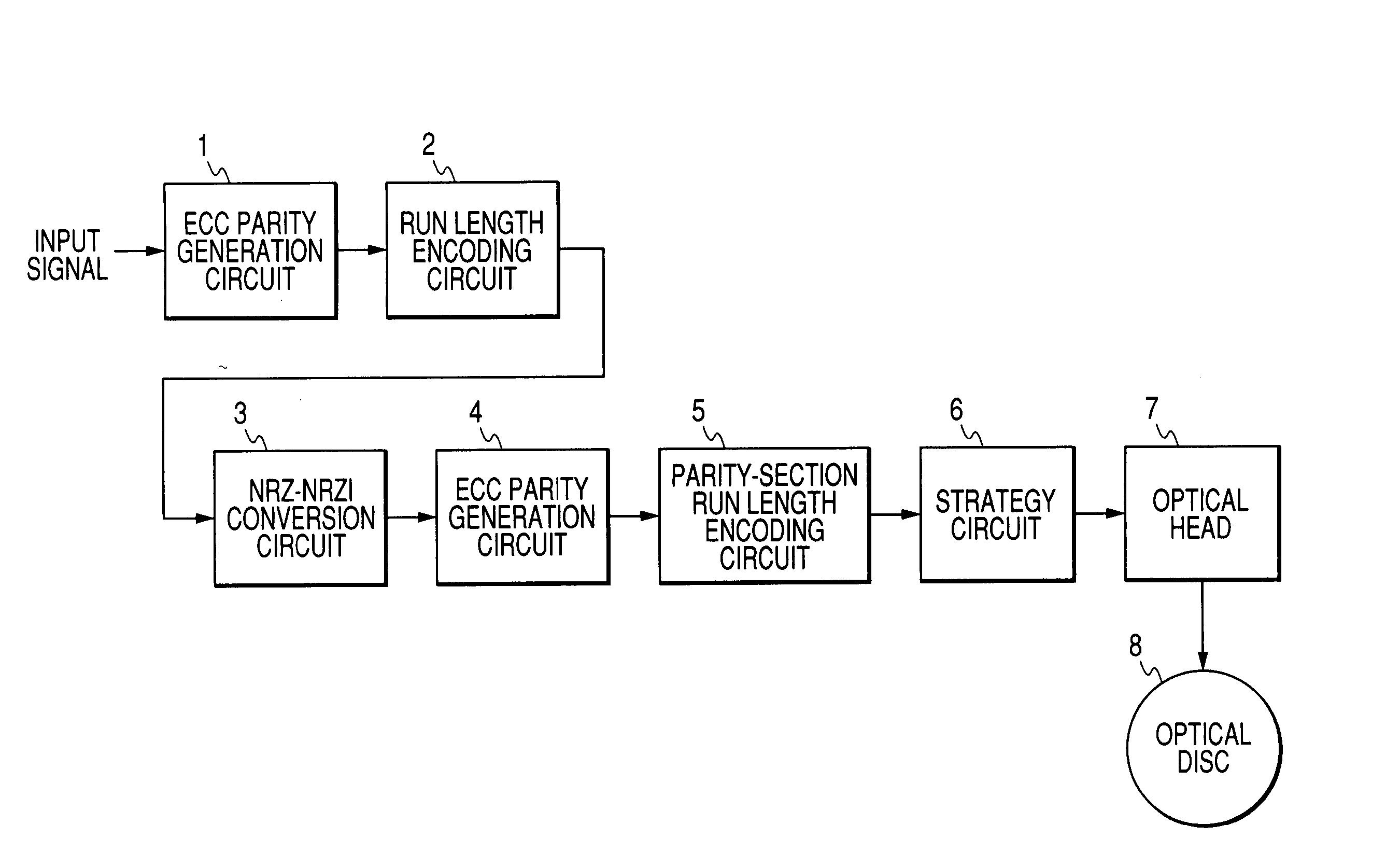
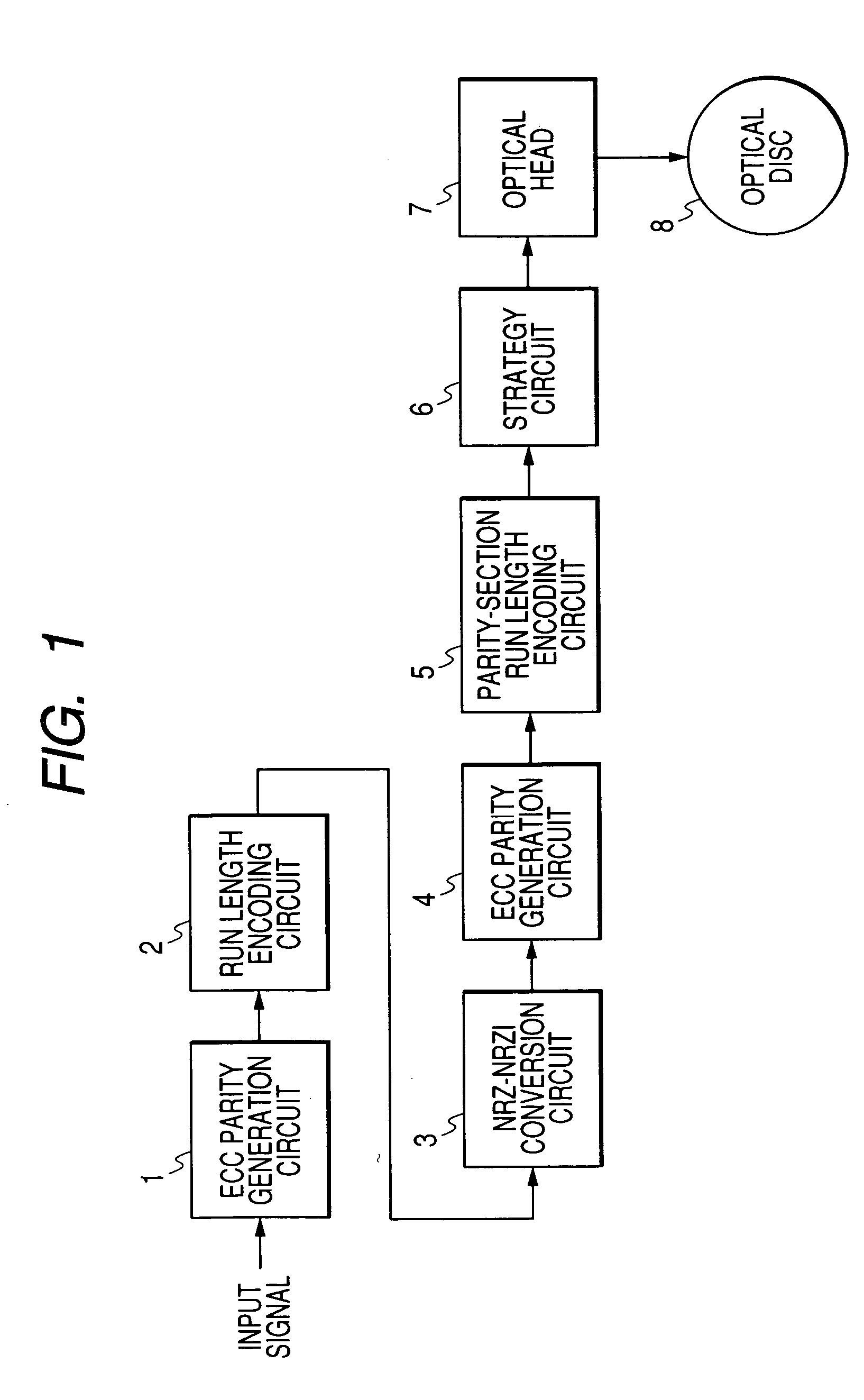
[0047]FIG. 1 shows a recording apparatus according to a first embodiment of this invention. The recording apparatus of FIG. 1 includes a first ECC parity generation circuit 1, a run length encoding circuit 2, an NRZ-NRZI conversion circuit 3, a second ECC parity generation circuit 4, a parity-section run length encoding circuit 5, and a strategy circuit 6 which are sequentially connected in that order. The strategy circuit 6 is followed by an optical head 7 which can act on an optical disc 8. The optical disc 8 is an information recording medium.
[0048] Input data (user data) representing digital information to be recorded is fed to the first ECC parity generation circuit 1. The first ECC parity generation circuit 1 produces first ECC (error checking and correcting) parity signals in response to the input data according to a first prescribed error correction scheme. The first ECC parity signals correspond to outer code words and include, for example, RS (Reed Solomon) code signals. ...
second embodiment
[0071]FIG. 6 shows a reproducing apparatus according to a second embodiment of this invention. As shown in FIG. 6, the reproducing apparatus includes an optical head 7, an A / D converter 11, an AGC and ATC circuit 12, a re-sampling DPLL (digital phase locked loop) 13, an adaptive equalization circuit 14, a viterbi decoder 15, a sync signal detection circuit 16, a parity-section run length decoding circuit 17, a first ECC circuit 18, an NRZI-NRZ conversion circuit 19, a run length decoding circuit 20, and a second ECC circuit 21 which are sequentially connected in that order. Furthermore, the first ECC circuit 18 and the second ECC circuit 21 are directly connected. The optical head 7 can act on an optical disc 8. The optical disc 8 is an information recording medium. In general, digital information has been recorded on the optical disc 8 by the recording apparatus of FIG. 1.
[0072] The optical head 7 reads out a recorded signal from the optical disc 8. The read-out signal contains in...
third embodiment
[0093]FIG. 10 shows a recording apparatus according to a third embodiment of this invention. The recording apparatus of FIG. 10 is similar to that of FIG. 1 except for design changes described hereafter.
[0094] The recording apparatus of FIG. 10 includes a run length encoding circuit 2A and a parity-section run length encoding circuit 5A instead of the run length encoding circuit 2 and the parity-section run length encoding circuit 5 (see FIG. 1). The run length encoding circuit 2A is connected with the parity-section run length encoding circuit 5A.
[0095] The run length encoding circuit 2A receives the information code words from the first ECC parity generation circuit 1. In addition, the run length encoding circuit 2A receives a condition signal from the parity-section run length encoding circuit 5A which represents the result of the run length encoding by the parity-section run length encoding circuit 5A. The run length encoding circuit 2A implements the run length encoding (the ...
PUM
 Abstract
Description
Claims
Application Information