Device for applying cryogenic composition and method of using same

a technology of cryogenic composition and device, which is applied in the direction of manufacturing tools, container discharge methods, mechanical instruments, etc., can solve the problems of cratering, cracking and failure of the entire insert along the cutting edge, and abrasion between the cutting insert and the workpi

Inactive Publication Date: 2006-06-15
COOL CLEAN TECH
View PDF38 Cites 101 Cited by
  • Summary
  • Abstract
  • Description
  • Claims
  • Application Information

AI Technical Summary

Problems solved by technology

Among the causes of failure of cutting inserts employed in prior art machining operations are abrasion between the cutting insert and workpiece, and a problem known as cratering.
Cratering results from the intense heat developed in the formation of the chips and the frictional engagement of the chips with the cutting insert.
If the craters are too deep, the entire insert is subject to cracking and failure along its cutting edge, as well as along the sides of the insert upon contact with the workpiece.
Cratering has become a particular problem in recent years due to the development and extensive use of hard alloy steels, high strength plastics and composite materials formed of high tensile strength fibers coated with a rigid matrix material such as epoxy.
Prior attempts to avoid cratering and wear of the insert due to abrasion with the workpiece have provided only modest increases in tool life and efficiency.
Although extremely hard, tungsten carbide inserts are brittle and are subject to chipping which results in premature failure.
The primary problem with flood cooling is that it is ineffective in actually reaching the cutting area.
A common problem with such apparatuses, however, is that coolant in the form of an oil-water or synthetic mixture, at ambient temperature, is directed across the top surface of the insert toward the cutting area without sufficient velocity to pierce the heat barrier surrounding the cutting area.
As a result, the coolant fails to reach the boundary layer or interface between the cutting insert and workpiece and / or the area on the workpiece where the chips are being formed before becoming vaporized.
In addition, this failure to remove heat from the cutting area creates a significant temperature differential between the cutting edge of the insert which remained hot, and the rear portion of the insert which was cooled by coolant, causing thermal failure of the insert.
Another serious problem in present day machining operations involves the breakage and removal of chips from the area of the cutting insert, tool holder and the chucks which mount the workpiece and tool holder.
If chips are formed in continuous lengths, they tend to wrap around the tool holder or chucks which almost always leads to tool failure or at least requires a periodic interruption of the machining operation to clear the area of impacted or bundled chips.
This is particularly disadvantageous in flexible manufacturing systems in which the entire machining operation is intended to be completely automated.
Flexible manufacturing systems are designed to operate without human assistance and it substantially limits their efficiency if a worker must regularly clear impacted or bundled chips.

Method used


Image

  • Device for applying cryogenic composition and method of using same
  • Device for applying cryogenic composition and method of using same
  • Device for applying cryogenic composition and method of using same

Examples


Embodiment Construction

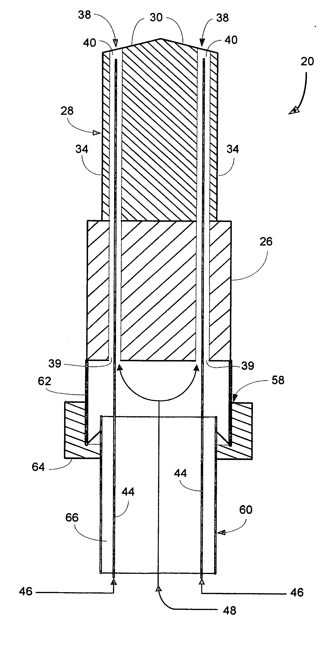
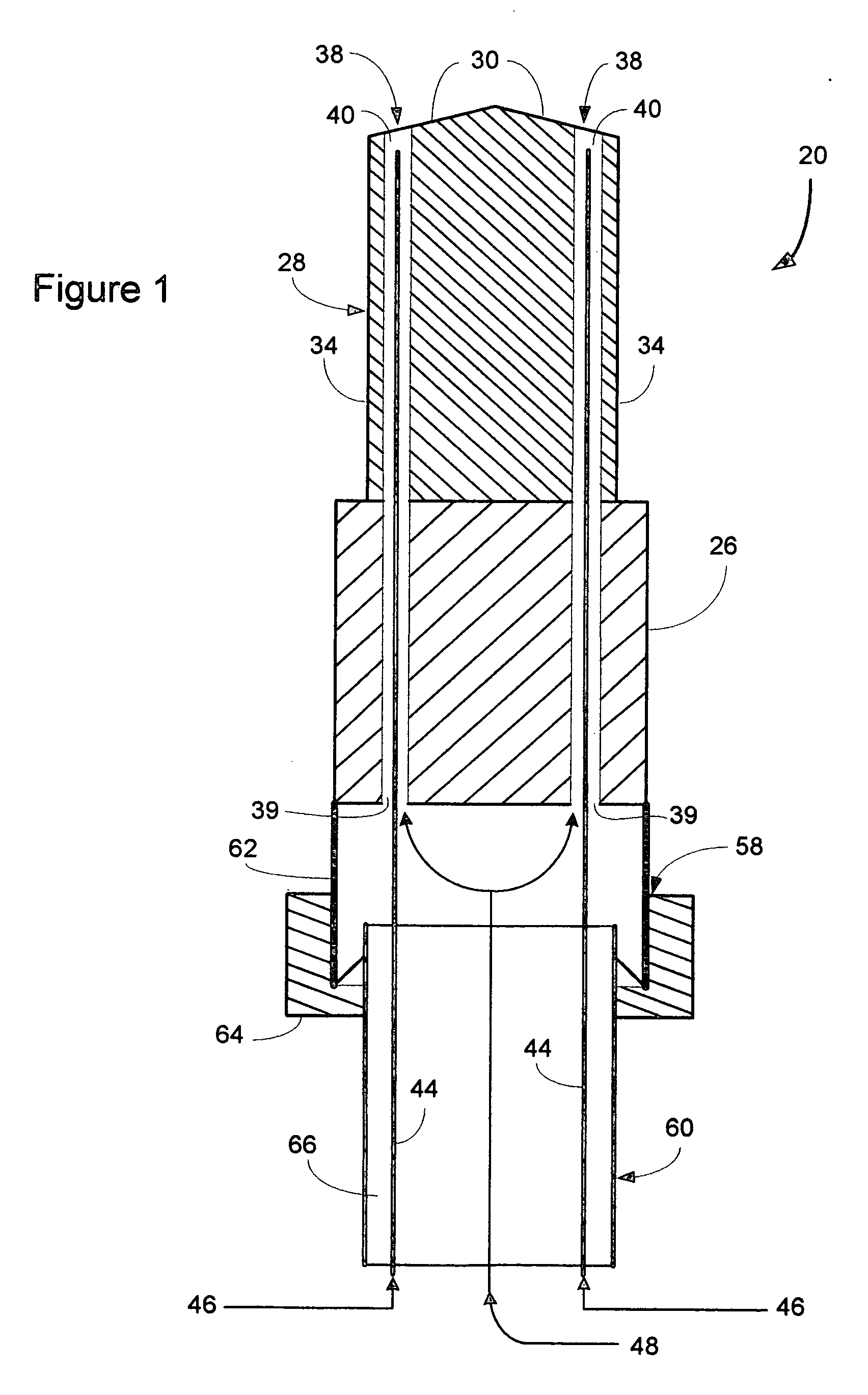
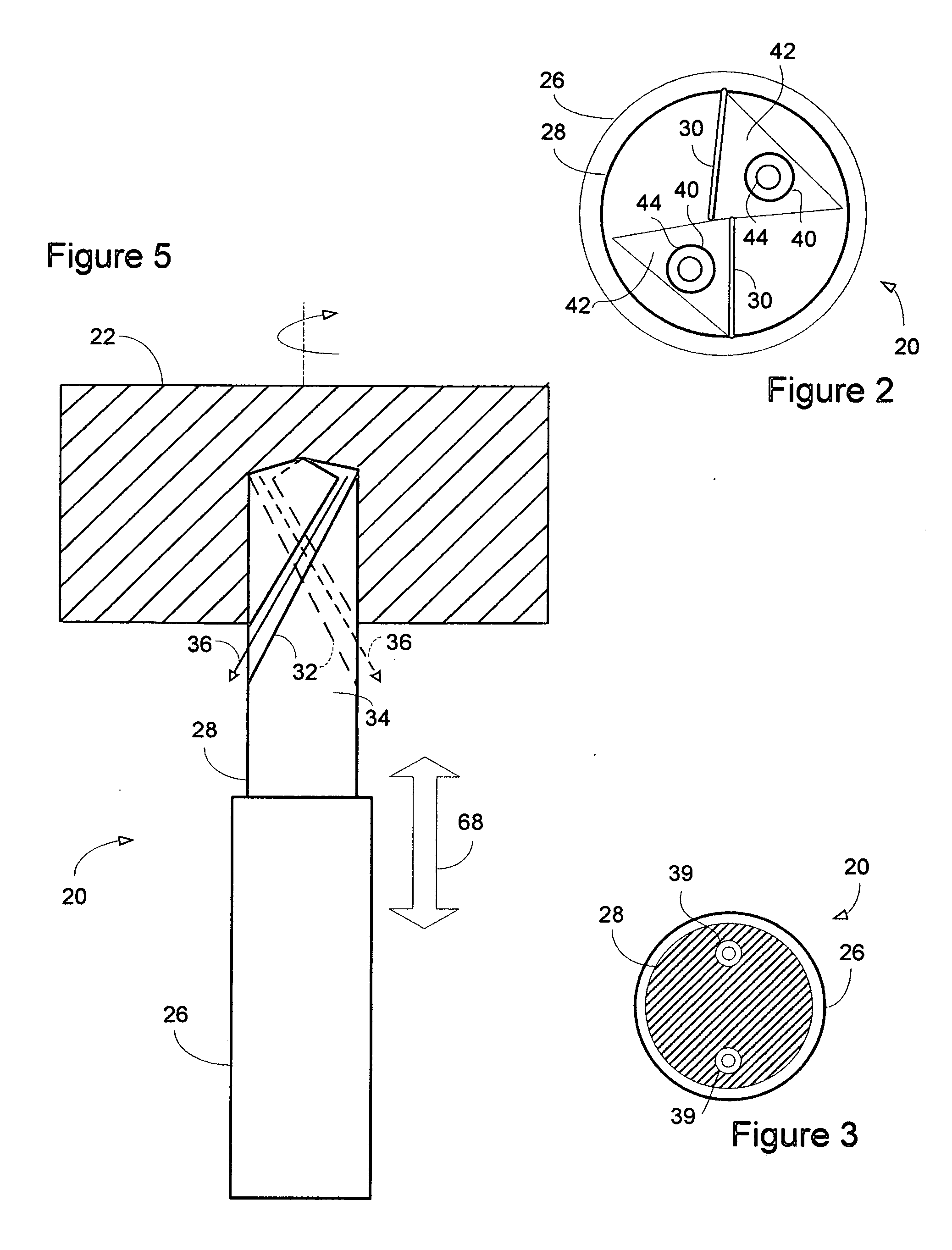
[0021] A dual ported spray-through machining tool of the present invention is generally indicated at 20 in FIG. 1. The tool 20 is designed for simultaneously cutting a substrate workpiece 22 while delivering a cryogenic composite machining fluid or spray 24 to the workpiece for cooling or lubricating the workpiece, cooling the tool, or a combination of both. The machining tool 20 of the present invention generally comprises a shank or tool holder portion 26 with a bit portion 28 connected thereto. The shank 26 is preferably engageable with a suitable chuck (not shown) to operably position the machining tool 20 proximate the workpiece 22. The bit portion 28 includes various cutting edges 30 for contacting the workpiece 22. Evacuation channels 32, preferably in a semi-spiral configuration, are positioned on outer surfaces 34 of the bit 28 for directing spent gases and chips 36 formed during the machining process away from the workpiece 22, as illustrated in FIG. 2.

[0022] To deliver t...


PUM


Abstract

A device of the present invention for applying a cryogenic composition includes a machining tool or tool holder having a channel positioned therethrough and a capillary tube positioned within the channel. A dense cryogenic fluid is passed through the capillary tube while a diluent or propellant fluid is passed through the channel. The diluent or propellant fluid flows within the channel and about the capillary tube. Upon exiting the capillary tube, the dense fluid admixes with the diluent or propellant fluid to form a cryogenic composite fluid or spray. The cryogenic composite fluid or spray is selectively directed onto a substrate for cooling or lubrication purposes, or onto the machining tool for cooling purposes.

Description

CROSS-REFERENCE TO RELATED APPLICATION(S) [0001] This application claims the benefit U.S. Provisional Patent Application No. 60 / 635,399 filed on 13 Dec. 2004 entitled METHOD, PROCESS, CHEMISTRY AND APPARATUS FOR SELECTIVE THERMAL CONTROL, LUBRICATION AND POST-CLEANING A SUBSTRATE. BACKGROUND OF INVENTION [0002] The present invention generally relates to machining tools. More specifically, the present invention relates to a machining tool that can combine a cutting operation with selective thermal control and / or lubrication during a machining process. [0003] Most machining operations are performed by a cutting tool which includes a holder and one or more cutting inserts each having a top surface terminating with one or more cutting edges. The tool holder is formed with a socket within which the cutting inserts are clamped in place. The leading or cutting edge of an insert makes contact with the workpiece to remove material therefrom in the form of chips. A chip comprises a plurality ...

Claims


Application Information

Patent Timeline
Patent Type & Authority Applications(United States)
IPC IPC(8): F17C7/02
CPCB23B27/10B23B51/06B23Q11/1053B23Q11/1061
Inventor JACKSON, DAVID P.
Owner COOL CLEAN TECH
Why Eureka
Try Eureka