Cooling system for an on-board inert gas generating system

a technology of inert gas and cooling system, which is applied in the field of cooling system, can solve the problems of heavy, unreliable prior obiggs system, and high cost of both initial acquisition and non-military operation, and achieve the effect of reducing the possibility of combustion

Active Publication Date: 2006-06-15
PARKER INTANGIBLES LLC
View PDF14 Cites 6 Cited by
  • Summary
  • Abstract
  • Description
  • Claims
  • Application Information

AI Technical Summary

Benefits of technology

[0010] The present invention provides a system and method for reducing the possibility of combustion in aircraft fuel tanks by replacing air in the ullage of the fuel tank with an inert gas that has been separated out from the engine bleed air.
[0012] In another embodiment of the invention there is provided a method for generating inert gas. Air is firstly compressed into compressed air. Thereafter, the compressed air is introduced into multiple hollow fiber membranes. The compressed air is separated into nitrogen Enriched Air (NEA) within the hollow fiber membranes and oxygen enriched air (OEA) in a space surrounding the hollow fiber membranes. At the same time, cooling air is introduced into the space to cool the NEA within the hollow fiber membranes into cooled NEA. The cooled NEA is then expelled from the hollow fiber membranes, and the OEA and the cooling air is expelled from the space. Accordingly, the present invention enhances the performance of the system by cooling the NEA flow. This is accomplished by transferring the heat of the NEA flow to the cooling air flow from the external surface of the hollow fibers. This significantly simplifies the system and eliminates the need for a separate heat exchanger.

Problems solved by technology

Prior OBIGGS systems have proved relatively unreliable, heavy, and costly for both initial acquisition and non-military operation.
To ensure that the inert gas is at a sufficiently cool temperature, current OBIGGS systems typically pre-cool the air entering the ASM of the OBIGGS system using bulky and expensive heat exchangers.

Method used


Image

  • Cooling system for an on-board inert gas generating system
  • Cooling system for an on-board inert gas generating system
  • Cooling system for an on-board inert gas generating system

Examples


Embodiment Construction

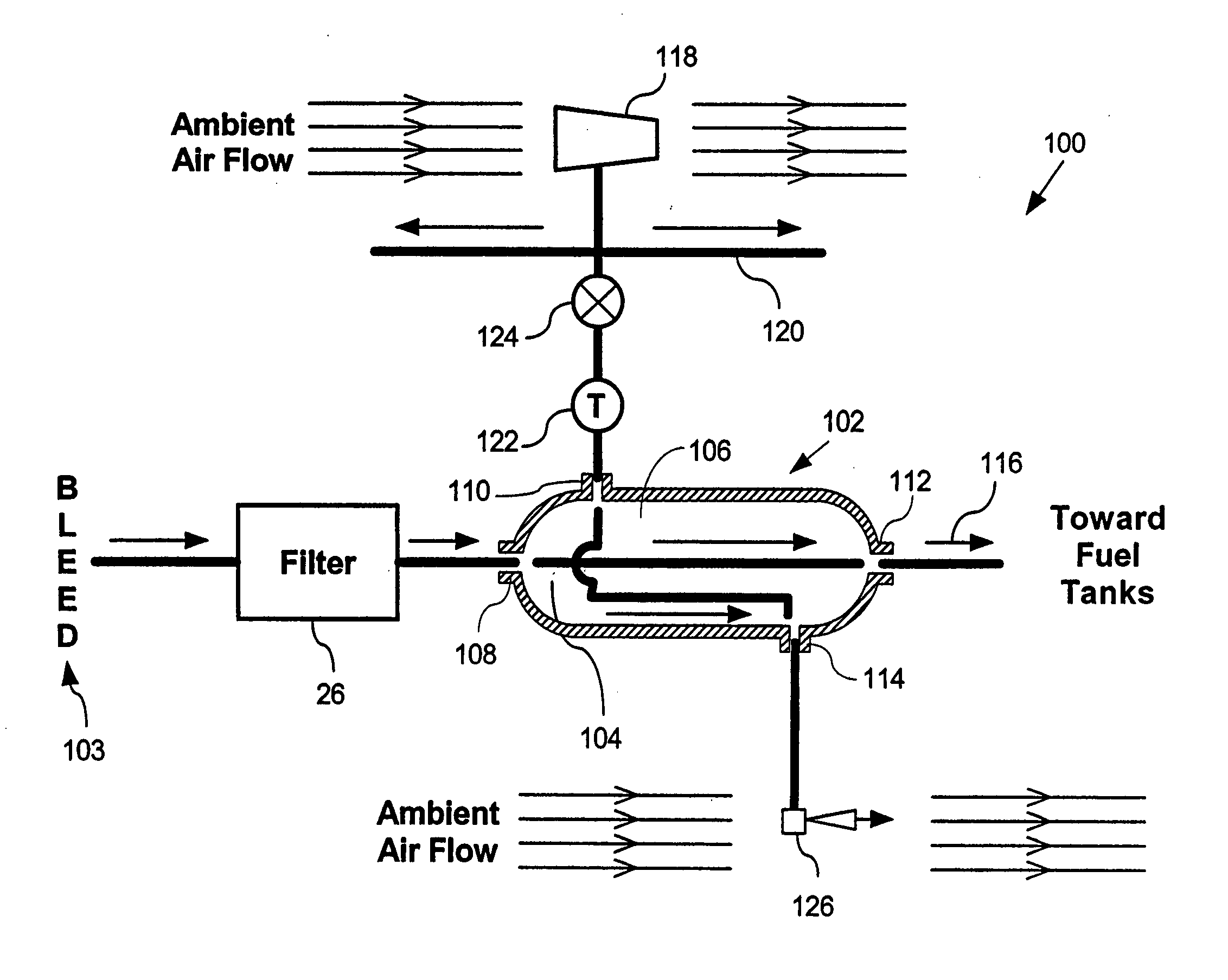
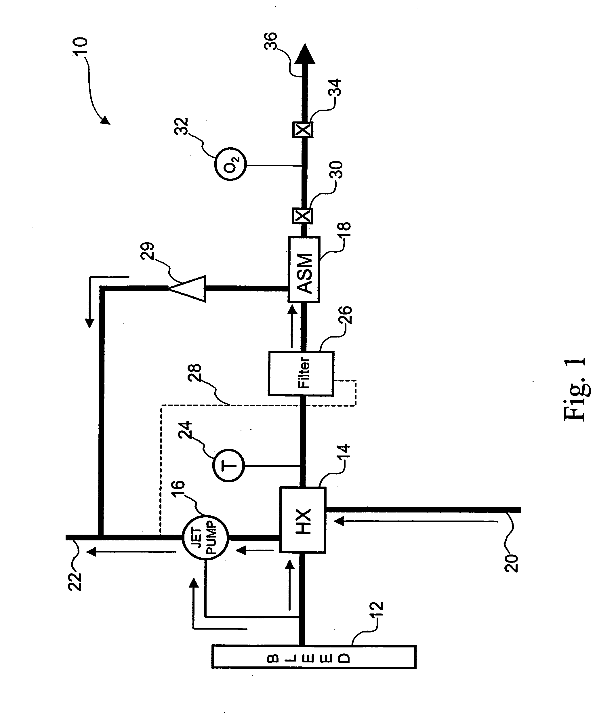
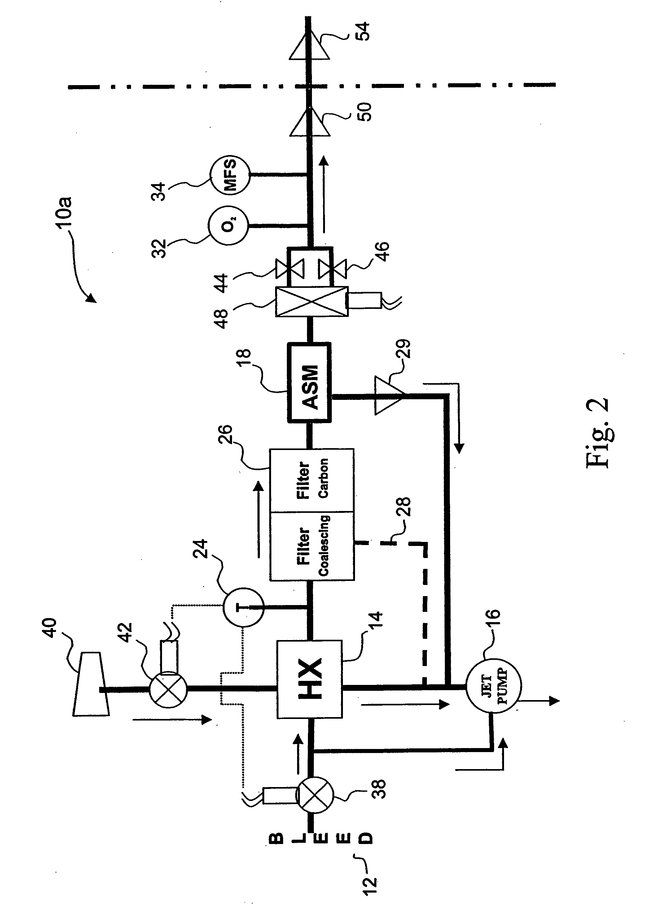
[0024] As illustrated in FIG. 1, system 10 according to one embodiment of the invention uses aircraft engine bleed air 12 that is supplied under conditions of elevated temperature and elevated pressure to generate gas for inerting aircraft fuel tanks. It will be appreciated by persons skilled in the art that the present invention is equally useful for inerting cargo holds and other void spaces. Engine bleed air is typically supplied from taps in the compressor section of the aircraft engines at temperatures in the range of 300° F.-400° F. and at pressures in the range of 10-45 psig depending on compressor rotation speed. It is typically used as a utility source of pressurized air on board aircraft. System 10 operates whenever bleed air is available and, thus, avoids the use of compressors or complex control valves.

[0025] Bleed air 12 is introduced at one end of system 10 and nitrogen-enriched air (NEA) is produced from the other end. Bleed air 12 flows under pressure and temperatur...


PUM


Abstract

The inert gas generating system includes a compressed air source, a cooling air source, and a separation module. The separation module includes first and second inlets and outlets. The first inlet is coupled to the compressed air source. The first outlet is coupled to the first inlet via a bundle of hollow fiber membranes. The second inlet is coupled to the cooling air source, and the second outlet is coupled to the second inlet via a space surrounding the bundle of hollow fiber membranes.

Description

CROSS REFERENCE TO RELATED APPLICATIONS [0001] This application is a continuation of prior U.S. patent application Ser. No. 10 / 794,279, filed Mar. 5, 2004, which claims the benefit of U.S. Provisional Patent Application No. 60 / 453,102, filed Mar. 7, 2003, all of which are incorporated by reference herein in their entirety.BACKGROUND OF THE INVENTION [0002] 1. Field of the Invention [0003] The invention relates generally to cooling systems. More specifically, the invention relates to a system and method for cooling a nitrogen enriched air stream as it passes through an air separation module (ASM) of an On-board Inert Gas Generating Systems (OBIGGS). [0004] 2. Description of Related Art [0005] The energy requirements of most modern aircraft are supplied by combusting aviation gasoline, which is typically stored in fuel tanks within an aircraft's wings. Such fuel tanks also contain an explosive fuel / air mixture in the area above the fuel, otherwise known as the ullage. Accordingly, man...

Claims


Application Information

Patent Timeline
Patent Type & Authority Applications(United States)
IPC IPC(8): B01D53/22F25D9/00F25J3/00A62B7/14A62C99/00B64D10/00
CPCA62B7/14A62C99/0018B01D53/22B01D63/02B65D90/44B01D2313/22B64D10/00B64D2013/0677B64D37/32B01D2313/18B01D2313/221
Inventor JONES, PHILIP E.
Owner PARKER INTANGIBLES LLC
Why Eureka
Try Eureka