Oil tank for dry sump engines

a dry sump engine and oil tank technology, applied in the direction of engine lubrication, mechanical equipment, pressure lubrication with lubrication pump, etc., can solve the problems of reducing the ability of rust protection, the possibility of condensation formation, and the degradation of oil, so as to reduce the flow of condensation droplets.

Active Publication Date: 2006-06-15
ASTON MARTIN LAGONDA LIMITED
View PDF3 Cites 10 Cited by
  • Summary
  • Abstract
  • Description
  • Claims
  • Application Information

AI Technical Summary

Benefits of technology

[0006] According to the invention there is provided an oil tank for a dry sump engine, the oil tank having a housing having an upper region and a lower region in which the oil is contained, the lower region having an oil outlet and the upper region having an air outl

Problems solved by technology

Unfortunately, this means that a quantity of air and other gases is returned to the oil tank together with the returned oil.
It is a disadvantage of such an oil tank that when the air leaves the centrifugal de-aerator there is opportunity for condensation to form due to the temper

Method used


Image

  • Oil tank for dry sump engines
  • Oil tank for dry sump engines
  • Oil tank for dry sump engines

Examples


Embodiment Construction

(s)

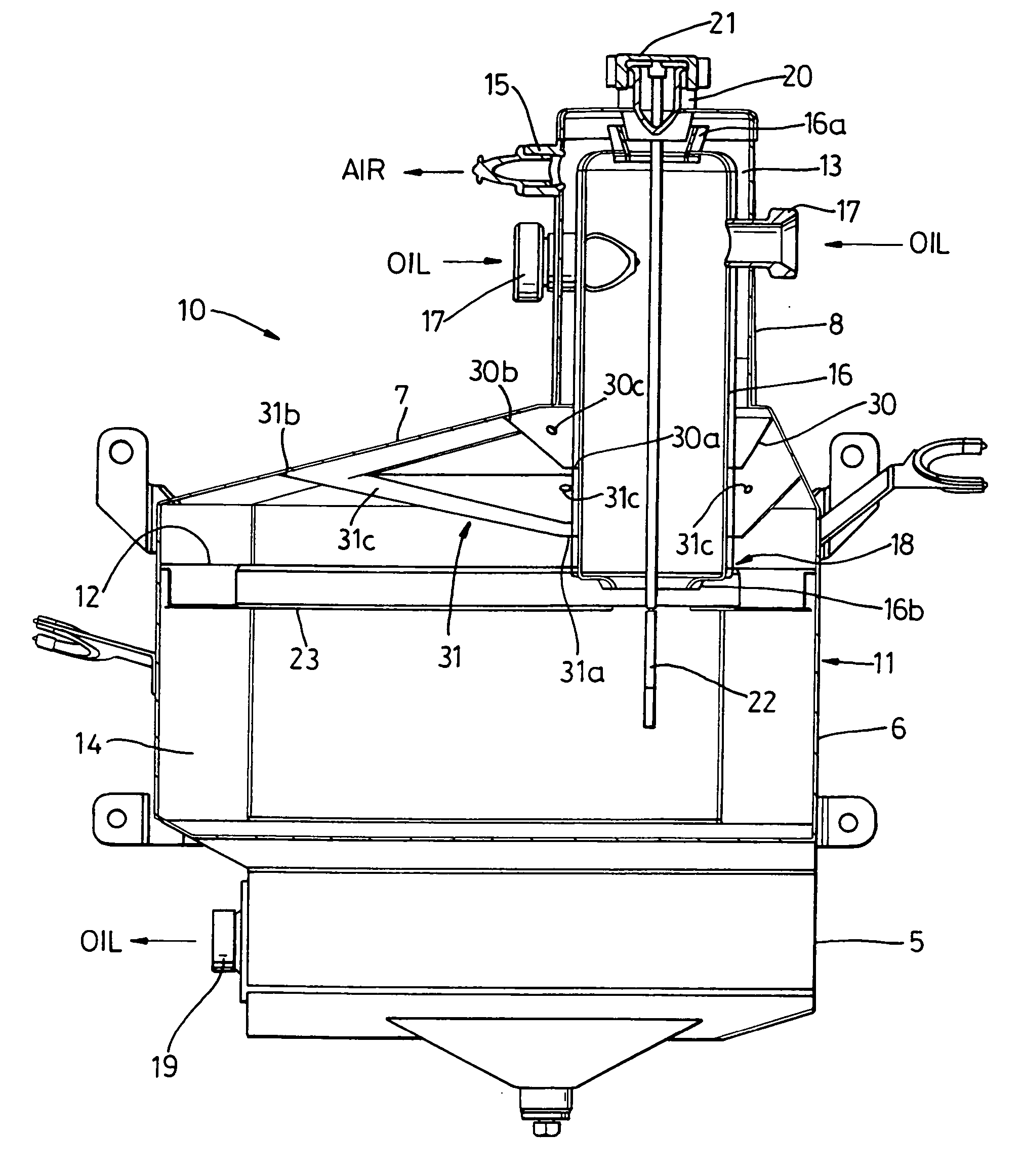
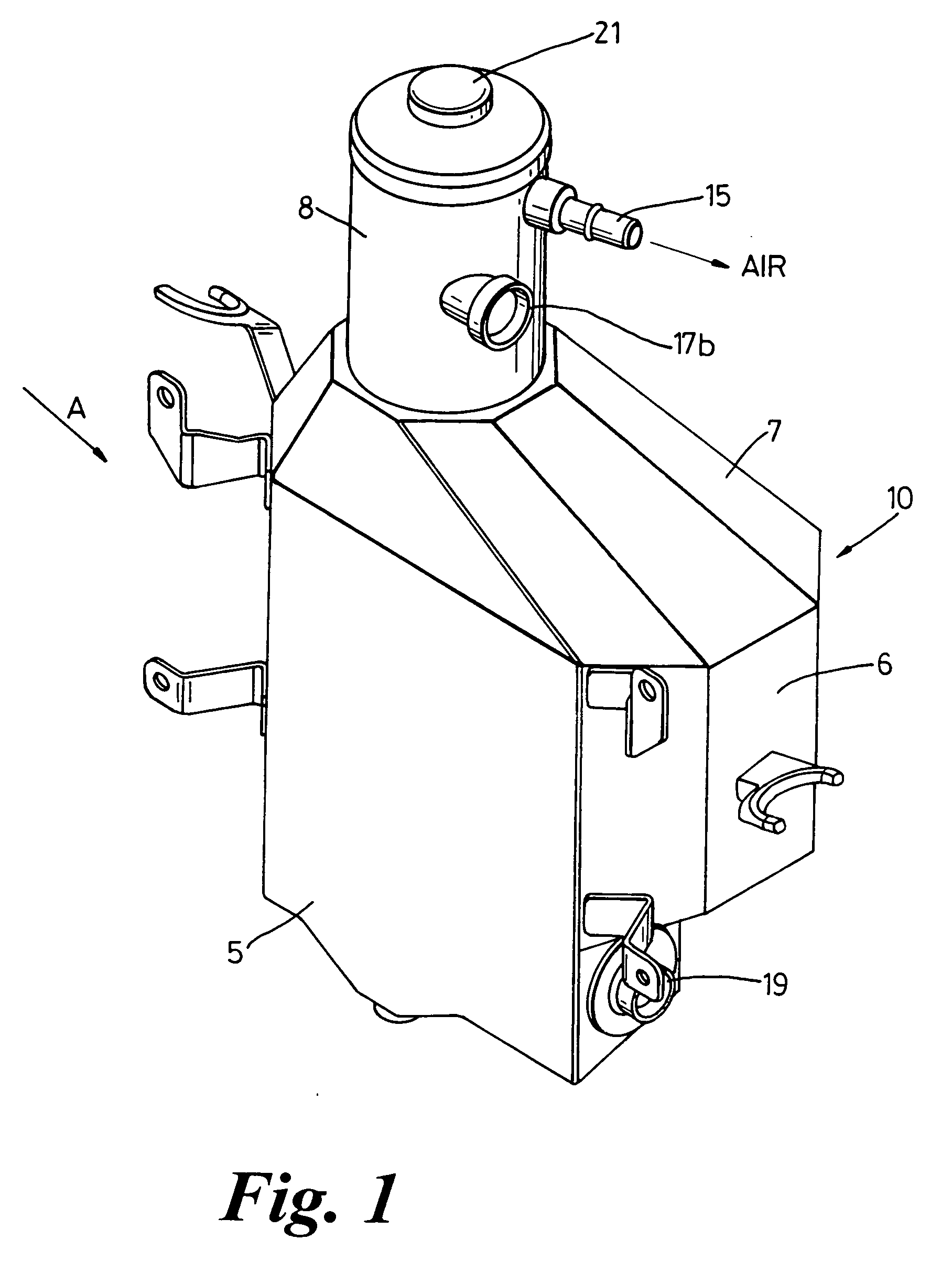
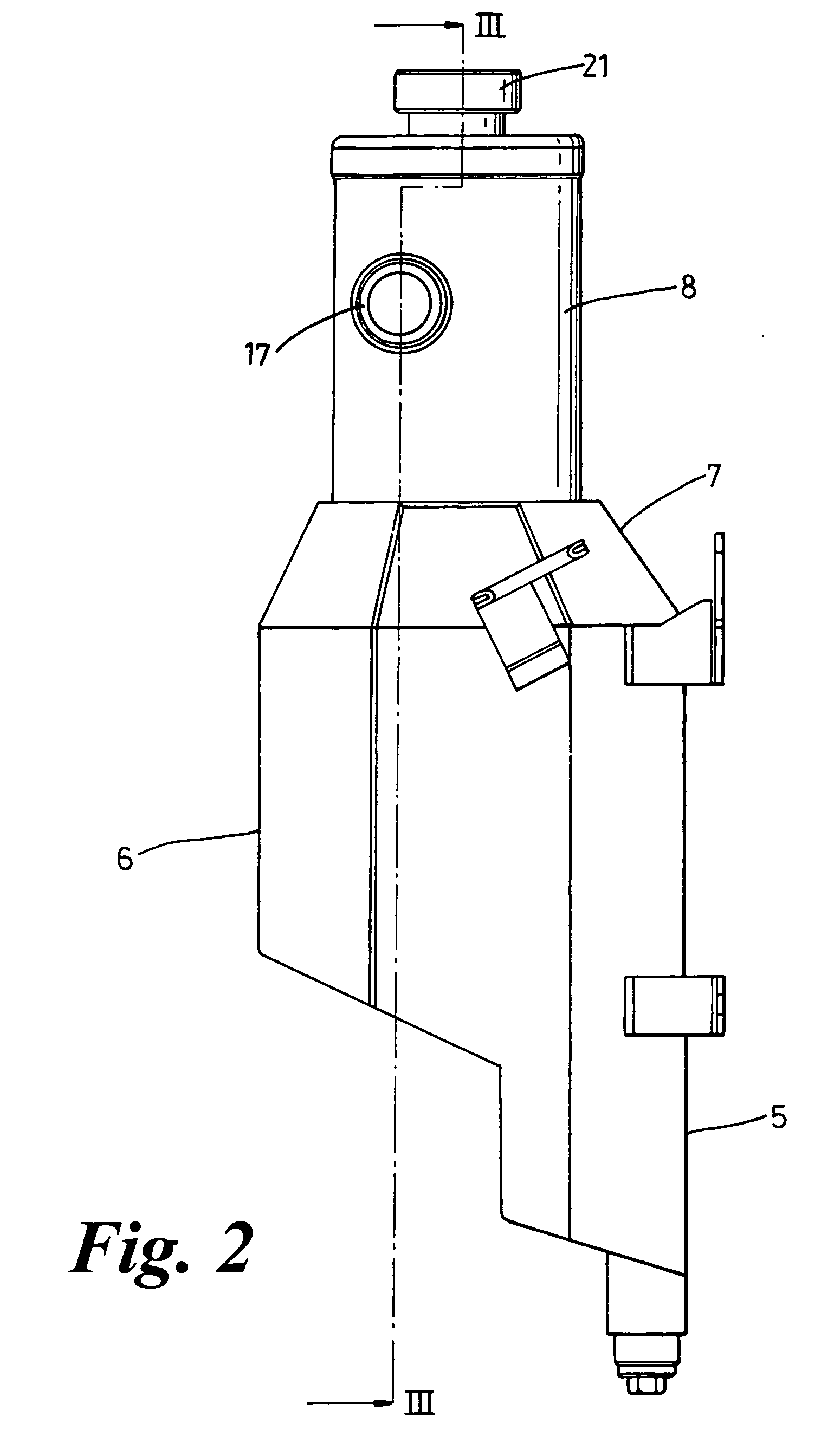
[0016] With reference to the drawings, there is shown an oil tank 10 which is formed from metal sheets. The oil tank comprises a tank bottom 5, side walls 6 and a tank lid 7 having a cylindrical neck 8, all together forming a housing 11.

[0017] The housing 11 has a baffle plate 12 which defines two substantially upright compartments. These compartments are conveniently referred to as a breather volume, upper region or top compartment 13 and an oil volume, lower region or bottom compartment 14 in the following description. The baffle plate 12 carries a plate gauze oil filter element 23.

[0018] The top compartment 13 is provided with an air outlet 15 and a centrifugal de-aerator or gas separator 16. The centrifugal de-aerator 16 comprises a non-rotating upright tube or swirl tube which has a tangentially extending oil inlet 17 in order to give a circular flow to the air and oil mixture entering by way of the inlet 17 into the swirl tube 16. As shown in the drawings, the swirl tube ...


PUM

PropertyMeasurementUnit
Areaaaaaaaaaaa

Abstract

An oil tank for a dry sump engine has a housing having an upper region and a lower region in which the oil is contained. The lower region has an oil outlet to feed a pump which supplies oil to the engine. The upper region houses a swirl tube connected to an oil inlet for air to separate from the incoming oil. The upper region includes an air outlet and is provided with two dished baffle plates each shaped to form a collector area which slopes towards the swirl tube in order to reduce droplets of condensation formed in the upper region flowing into the lower region. The wall of the swirl tube is heated by the incoming oil to promote vaporisation of droplets of condensation collected in the collector area.

Description

FIELD OF THE INVENTION [0001] The present invention relates to an oil tank for a dry sump engine of a motor vehicle, and more particularly to an improved system for reducing condensation in an oil tank. BACKGROUND AND SUMMARY OF THE INVENTION [0002] Typically, an internal combustion engine with dry sump lubricating system has a feed pump which supplies lubricating oil from an oil tank disposed outside the engine body to the moving parts in the engine. Oil which has dropped down into a crankcase after circulating through the engine is immediately picked up from the crankcase and sent back into the oil tank by means of a return pump. To ensure that the crankcase does not fill with oil, the pumping capacity of the return pump is greater than that of the feed pump. Unfortunately, this means that a quantity of air and other gases is returned to the oil tank together with the returned oil. [0003] FR2028926 describes an oil tank in which a centrifugal de-aerator is housed in the top of the...

Claims


Application Information

Patent Timeline
IPC IPC(8): F01M1/10F01M11/00
CPCF01M11/00F01M2013/0427F16N39/002B01D19/00F01M1/10F16N39/00
Inventor RICHARDS, MATTHEW
Owner ASTON MARTIN LAGONDA LIMITED
Why Eureka
Try Eureka