
Magnetorheological device and system and method for using the same

Inactive Publication Date: 2006-06-15
GM GLOBAL TECH OPERATIONS LLC
View PDF11 Cites 20 Cited by
  • Summary
  • Abstract
  • Description
  • Claims
  • Application Information

AI Technical Summary

Benefits of technology

[0006] Further embodiments of the invention include a method of controlling a vehicle suspension damping system. Signals from a plurality of sensors are received at a controller. The signals are analyzed, and an activation signal is generated in response thereto. In response to the activation signal, a magnetorheological (MR) damper is activated so as to cause an increase in the shear strength of a MR fluid at the MR damper, an opposing torque action at a magnetic rotor of the MR damper, an opposing translation-to-rotation conversion action at a translation-to-rotation converter of the MR damper, and increased damping of translational motion between a first and a second portion of the MR damper absent complete restraint of the first portion with respect to the second portion.

Problems solved by technology

Such MR dampers, however, employ large quantities of MR fluid, such as in excess of one liter per vehicle, need special finishes on the piston rod and the inner surface of the cylinder wall, and need special seals to minimize abrasion from the MR fluid.

Method used


Image

  • Magnetorheological device and system and method for using the same
  • Magnetorheological device and system and method for using the same
  • Magnetorheological device and system and method for using the same

Examples


Embodiment Construction

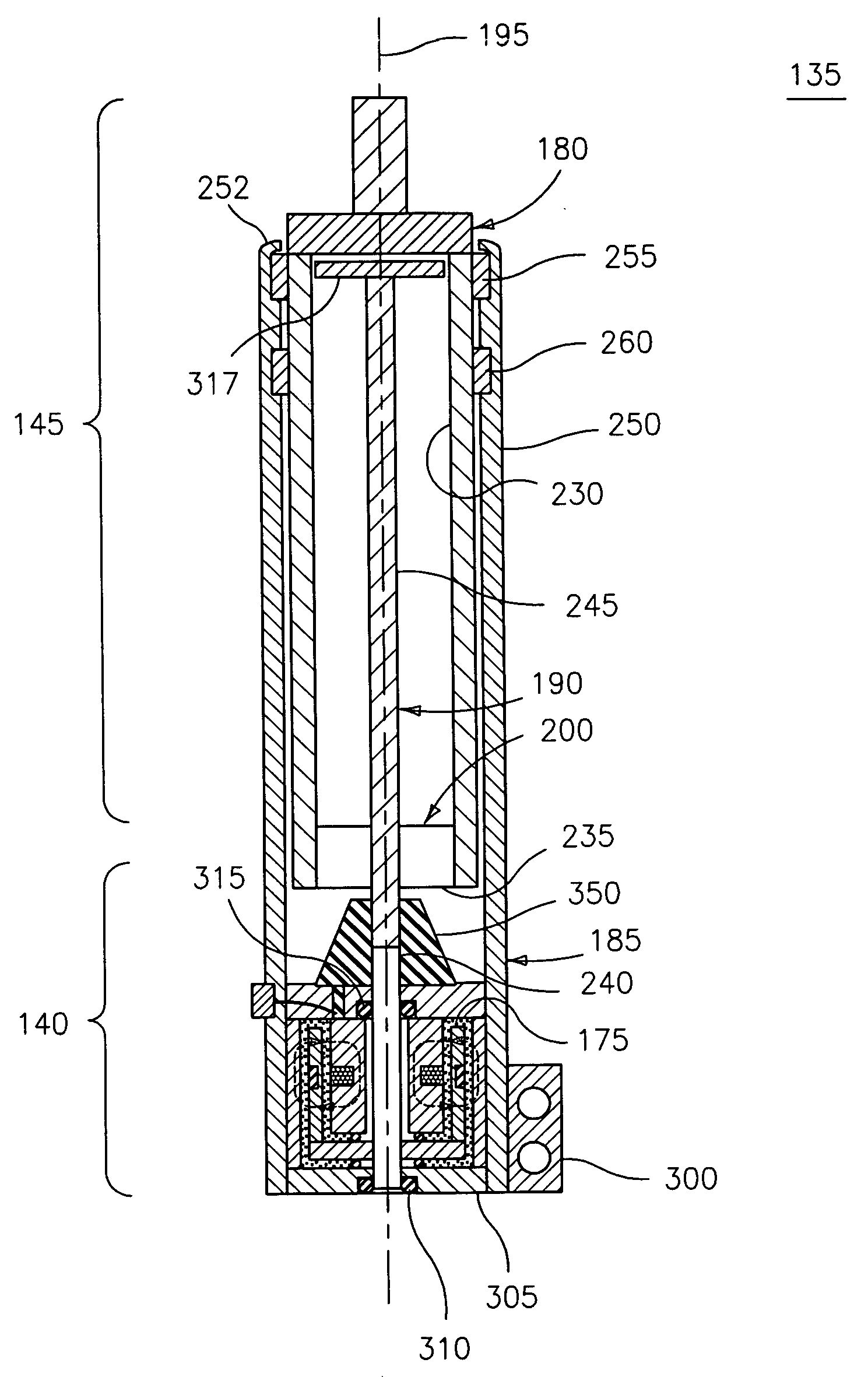
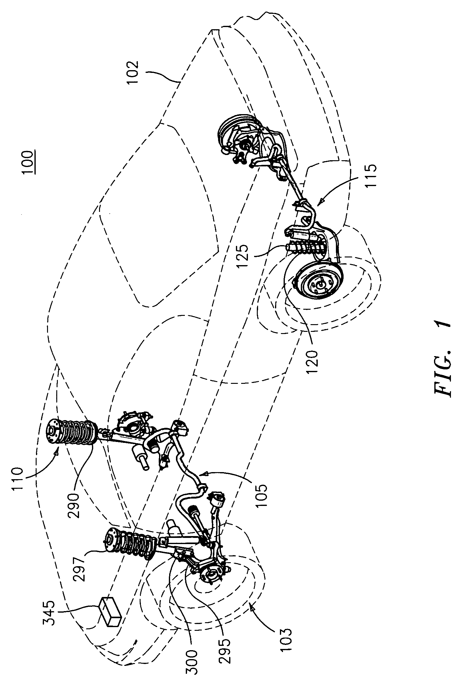
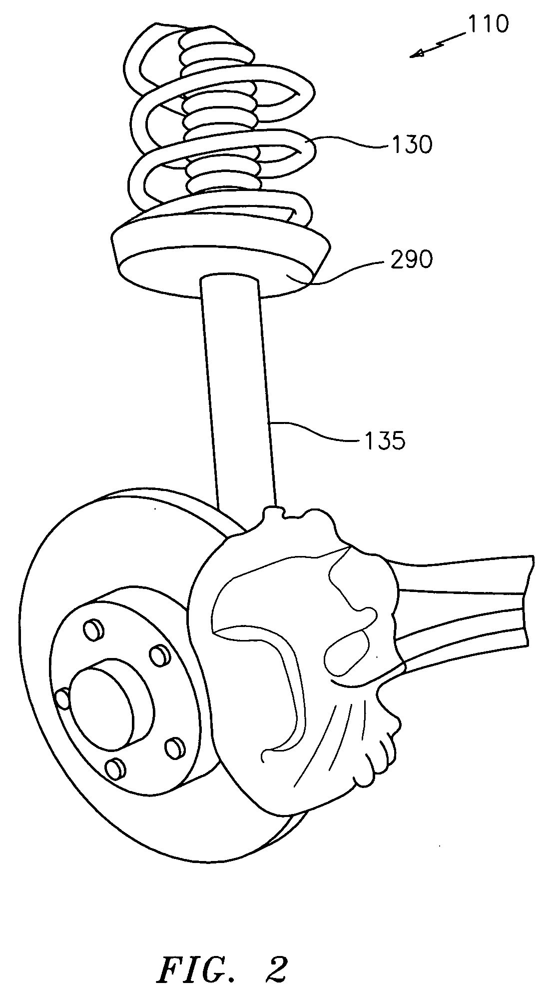
[0015] An embodiment of the invention utilizes controllable magnetorheological (MR) dampers in struts in the suspension system of a vehicle, thereby providing continuously controllable damping characteristics to the vehicle. Embodiments of the invention may use MR dampers in the front struts only, as replacements for the rear shock absorbers only, or for both purposes. In an embodiment, an electronic control module (controller) is used with suspension relative displacement sensors (one per wheel corner), and may also be used with a vehicle lateral accelerometer, a steering angle sensor and a vehicle speed sensor, for providing an excitation signal to the MR damper to allow for continuous modification of the damping characteristics of the vehicle suspension system. In response to the vehicle speed, steering angle and lateral acceleration, the control module may send a range of activation signals to the M dampers resulting in a range of vehicle suspension damping characteristics. Addi...


PUM


Abstract

A controllable magnetorheological (MR) damper having first, second and third portions is disclosed. The first and second portions have a translational degree of freedom therebetween, and the third portion has a rotational degree of freedom with respect to the first and second portions. The first and third portions are coupled via a translation-to-rotation converter, and the second and third portions are coupled via a magnetorheological (MR) fluid. A bearing is disposed between the first and second portions for supporting a side load therebetween, a magnetic field generator is in field communication with the magnetorheological fluid, and a signal path is in signal communication with the magnetic field generator. The third portion is rotationally responsive to translational motion between the first and second portions, the shear stress characteristic of the magnetorheological fluid is responsive to the magnetic field generator, and the magnetic field generator is controllably responsive to an excitation signal from the signal path.

Description

BACKGROUND OF THE INVENTION [0001] The present disclosure relates generally to a magnetorheological damper, and particularly to a controllable magnetorheological damper for damping the suspension system of a vehicle, and a control system and method for using the same. [0002] Vehicle suspension systems utilize damping devices or shock absorbers for controlling the vibrations of the body and wheel due to road disturbances imposed on the mass-spring system of the vehicle body, wheel and suspension springs. A vehicle suspension damper usually provides a resistive force proportional to the relative velocity between the body and the wheel. Passive dampers may employ an oil-filled cylinder and piston arrangement, while active and controllable dampers may employ a magnetorheological (MR) fluid-filled cylinder and piston arrangement where the viscosity of the MR fluid may be changed by the introduction of a magnetic field. Such MR dampers, however, employ large quantities of MR fluid, such a...

Claims


Application Information

Patent Timeline
IPC IPC(8): F16F15/03
CPCB60G17/0152B60G17/08B60G2200/142B60G2202/135B60G2202/312B60G2400/252B60G2400/821B60G2500/10B60G2800/162F16F9/535
Inventor NAMUDURI, CHANDRA S.
Owner GM GLOBAL TECH OPERATIONS LLC
Learn More