
Slab laser amplifier with parasitic oscillation suppression

a laser amplifier and parasitic oscillation technology, applied in laser details, active medium materials, active medium shape and construction, etc., can solve the problems of 4% reflectivity of polished uncoated air/glass interface, depletion of available gain, etc., to reduce the likelihood of parasitic oscillation and alleviate the need for reflective coatings

Active Publication Date: 2006-06-15
PANASONIC CORP
View PDF3 Cites 7 Cited by
  • Summary
  • Abstract
  • Description
  • Claims
  • Application Information

AI Technical Summary

Benefits of technology

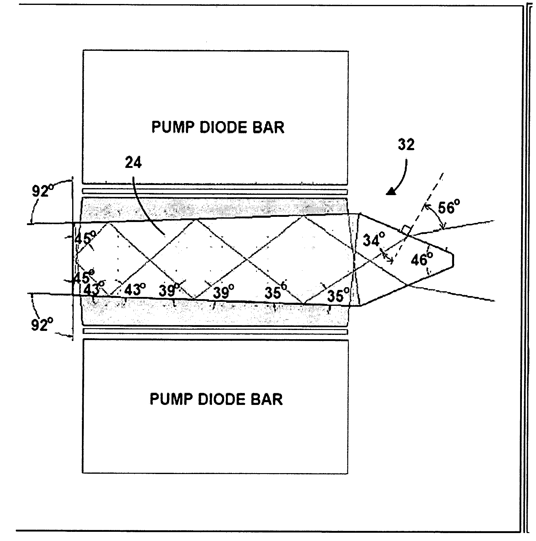
[0009] In accordance with the present invention, a slab laser amplifier with parasitic oscillation suppression has a plurality of angled pump faces related to one another in order to decrease likelihood of parasitic oscillations, with internal beam incidence angles at total internal reflection that alleviate need for reflective coatings.

Problems solved by technology

One problem encountered in the scenarios described above is that a polished uncoated air / glass interface has about 4% reflectivity.
This parasitic oscillation thereby depletes the available gain for the beam that we intend to amplify in the first place.

Method used


Image

  • Slab laser amplifier with parasitic oscillation suppression
  • Slab laser amplifier with parasitic oscillation suppression
  • Slab laser amplifier with parasitic oscillation suppression

Examples


Embodiment Construction

[0017] The following description of the preferred embodiments is merely exemplary in nature and is in no way intended to limit the invention, its application, or uses.

[0018] In the present invention, we are proposing to create a slab amplifier that is of a particular geometry that does not require additional optical coatings for either parasitic oscillation suppression, or for high efficiency reflection of the beam to be amplified. In particular, angular relation of the angled pump faces to one another minimizes the likelihood of parasitic oscillations. Also, the internal beam incidence angles at TIR (total internal reflection) can alleviate the need for reflective coatings on two polished main faces and a common polished end face of the amplifier used to reflectively direct a beam path of the amplified laser beam within the pumped volume of the gain material of the amplifier.

[0019] In some embodiments, the need for reflective coatings on these surfaces can be alleviated to point ...


PUM


Abstract

A slab laser amplifier with parasitic oscillation suppression has a plurality of angled pump faces related to one another in order to decrease likelihood of parasitic oscillations, with internal beam incidence angles at total internal reflection that alleviate need for reflective coatings. No polished surfaces of gain material comprising the amplifier are parallel to one another. A beam path within the gain material is such that all incident angles of the beam path upon the two main faces and the common end face are greater than a critical angle required for total internal reflection, thereby alleviating need for reflective coatings. Based on an index of refraction of the gain material, and based on a diameter of the laser beam, dimensions of the gain material are selected to maximize beam overlap in a pumped volume of the gain material.

Description

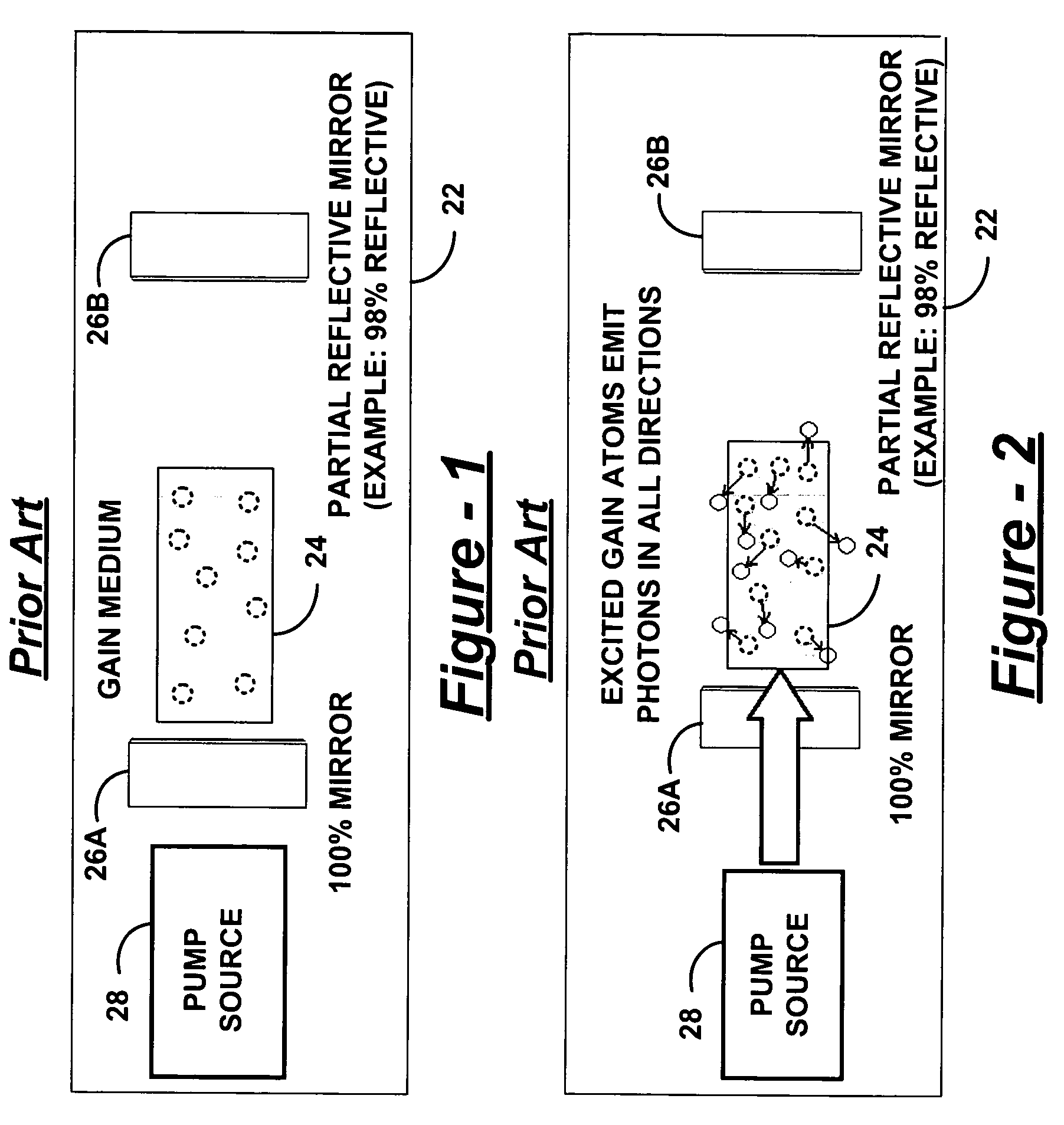
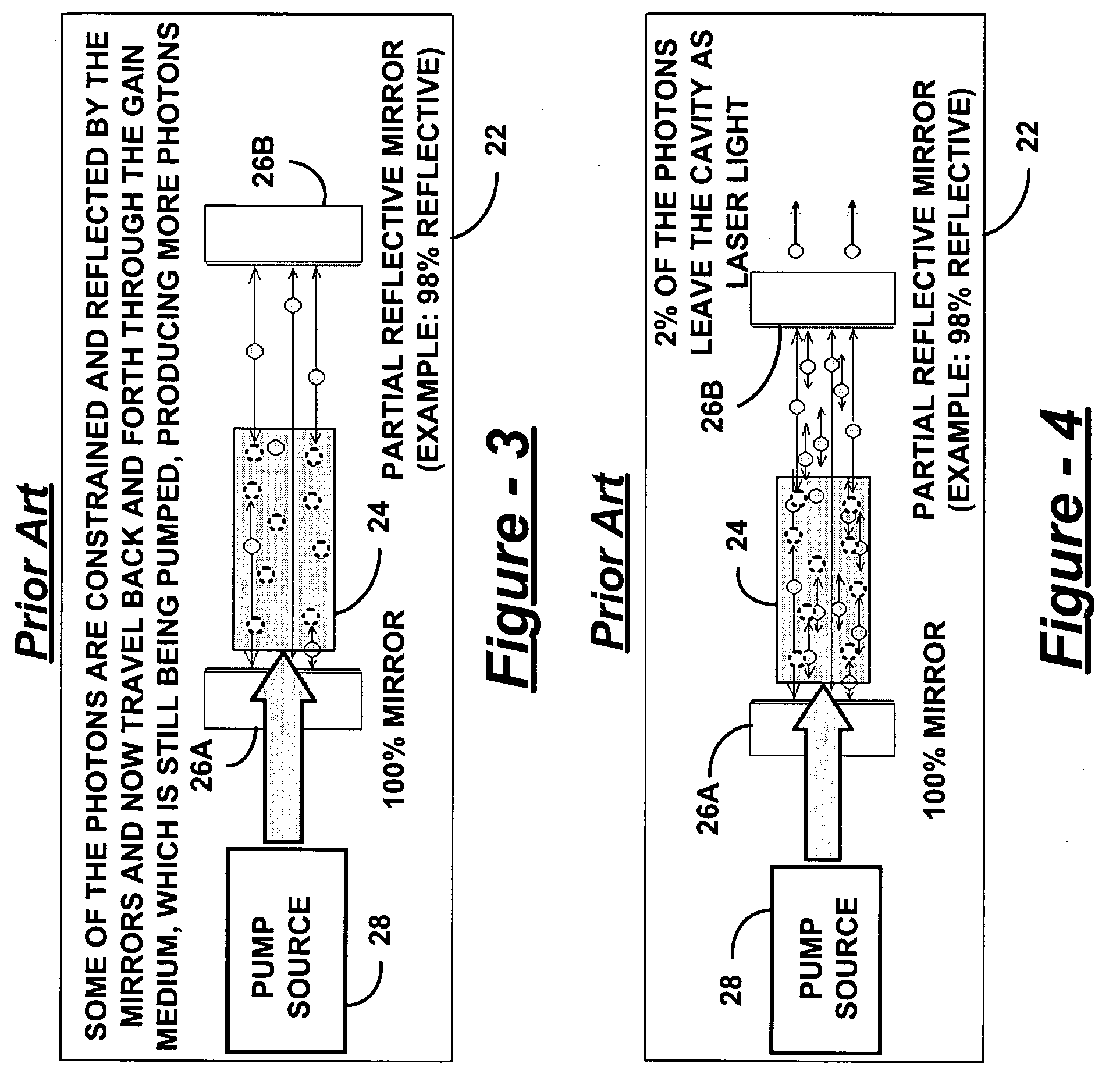
FIELD OF THE INVENTION [0001] The present invention generally relates to slab laser amplifiers, and relates in particular to a slab laser amplifier with parasitic oscillation suppression. BACKGROUND OF THE INVENTION [0002] Slab amplifiers are often used to boost output of a laser system by providing extractable energy from a pumped gain medium. The large surface area of the slab allows the pump energy to be spread over a wide volume of gain material to reduce heat effects. In general, a zig-zag pattern or tightly folded resonator (TFR) design makes use of multiple beam passes through the gain material to extract energy from the pumped region of the crystal. [0003] Referring to FIGS. 1-6, a brief overview is provided of how a laser amplifier works in accordance with the prior art. In FIGS. 1-4, a basic laser cavity 22 includes gain material 24. The cavity 22 also has at least two mirrors 26A and 26B, such as a 100% reflective mirror 26A and a 98% partially reflective mirror 26B. The ...

Claims


Application Information

Patent Timeline
Patent Type & Authority Applications(United States)
IPC IPC(8): H01S3/14
CPCH01S3/0606H01S3/0615H01S3/063H01S3/08095H01S3/0941H01S3/2333
Inventor FIRST, CRAIGLIU, XINBING
Owner PANASONIC CORP
Learn More