
X-ray diagnostic apparatus and method for operating an x-ray diagnostic apparatus for determining quality values

a diagnostic apparatus and x-ray technology, applied in the field of angiographic x-ray diagnostic apparatus, can solve problems such as the relevance of the overall system

Active Publication Date: 2006-06-15
SIEMENS HEALTHCARE GMBH
View PDF7 Cites 11 Cited by
  • Summary
  • Abstract
  • Description
  • Claims
  • Application Information

AI Technical Summary

Benefits of technology

[0062] These methods enable the visibility of guide wires and stents in x-ray images to be quantified under standardized recording conditions, thereby making possible image-quality certification of guide wires and stents in order to ensure a particular minimum quality in terms of visibility.

Problems solved by technology

However, they only take account of isolated technical issues and not the clinically relevant behavior of the overall system.

Method used


Image

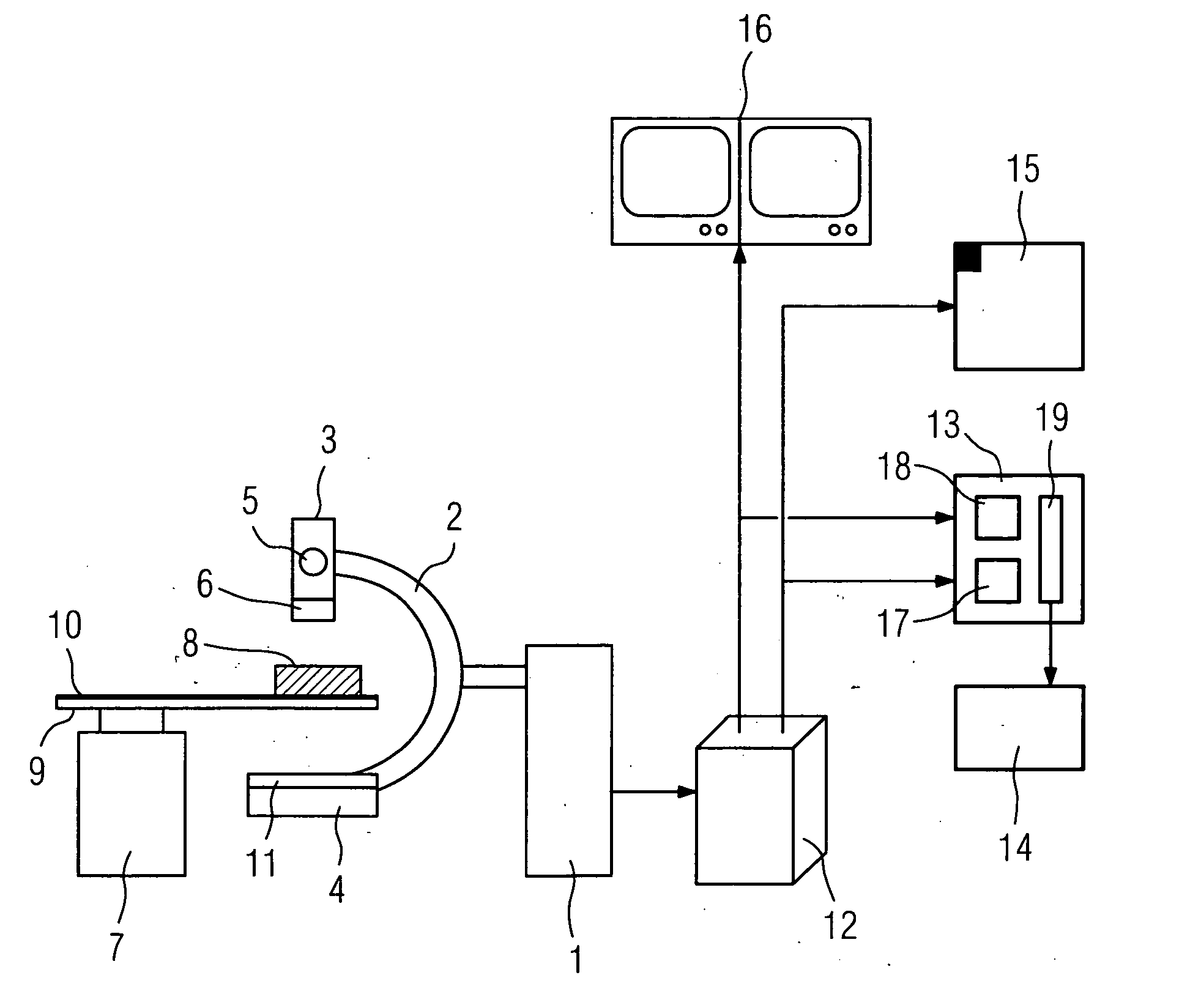
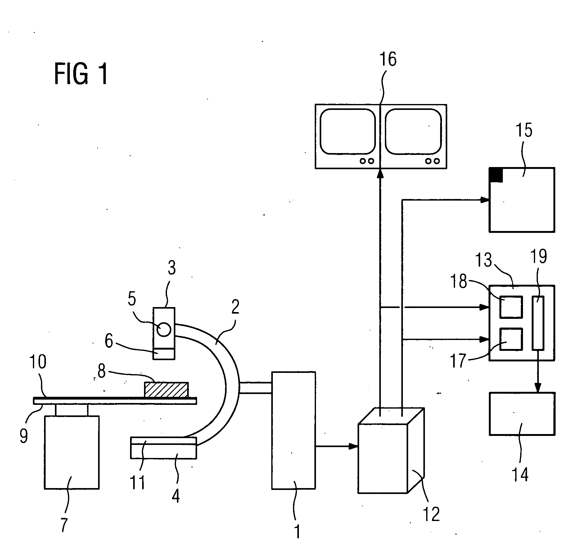
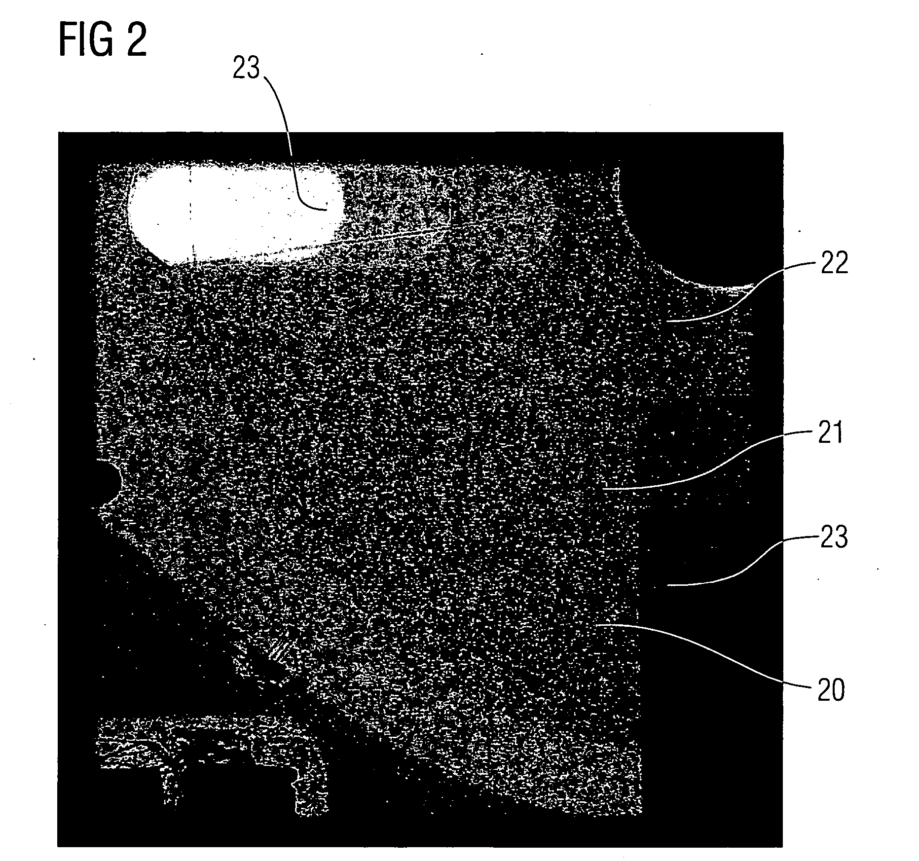
  • X-ray diagnostic apparatus and method for operating an x-ray diagnostic apparatus for determining quality values
  • X-ray diagnostic apparatus and method for operating an x-ray diagnostic apparatus for determining quality values
  • X-ray diagnostic apparatus and method for operating an x-ray diagnostic apparatus for determining quality values

Examples


first embodiment

[0080]FIG. 3 describes the x-ray diagnostic apparatus according to the invention, for which a quality value is obtained from the x-ray image of a guide wire 21 contained in the phantom 8. The x-ray diagnostic apparatus delivers a transducer signal 30 corresponding to the SID angulation (Source to Image Distance). From the transducer signal 30, a prediction stage 31 makes a prediction of the position of the guide wire 21. A lookup table (LUT) 32 contains the a priori knowledge concerning the shape of the guide wires 21 in the projection plane. This knowledge is retrieved and fed, together with the output signal of the prediction stage 31, to a device 33 for performing the Hough transformation known e.g. from U.S. Pat. No. 3,069,654. The shape of the guide wires 21 can be linear or square, thereby producing a straight line or a parabola.

[0081] In a subtraction stage 34, a background image 37 is extracted from a current image 36 extracted from a series of continuous images 35, the outp...

second embodiment

[0083]FIG. 4 describes the x-ray diagnostic apparatus according to the invention, in which a quality value is formed from the x-ray image of a stent 50 contained in the phantom 8. The stents 50 are located within a Region of Interest (ROI) 51 in continuous x-ray images 52 in which markers 22 are again disposed for better detection. The last of the continuous x-ray images 52 is the current x-ray image 53.

[0084] From the transducer signal 30 of the SID angulation, a prediction stage 54 makes a prediction of the position of the stent 50. A lookup table (LUT) 55 contains a priori knowledge about the shape of the stents 50 in the projection plane. This knowledge is retrieved and fed together with the output signal of the prediction stage 54 to a device 56 for taking the variance. The shape of the stents 50 can be linear or square, thereby producing straight lines or parabolas.

[0085] In the subtraction stage 34, the background image 37 is subtracted from a current x-ray image 53 taken fr...


PUM


Abstract

The invention relates to an angiographic x-ray diagnostic apparatus with an x-ray radiator having an x-ray tube, with a patient positioning table having a radiation-transparent positioning plate and mattress, with an x-ray detector, with an imaging system, an image processing unit and a measuring device to which the output signals of the x-ray detector are fed and which has a first device for determining a value determining the reproduction quality of clinically relevant objects, a second device for determining local variances of the noise in a homogenous image region of different x-ray images and a device for taking the ratio of the output values of the two devices.

Description

CROSS REFERENCE TO RELATED APPLICATIONS [0001] This application claims priority to the German application No. 10 2004 060 127.5, filed Dec. 13, 2004 which is incorporated by reference herein in its entirety. FIELD OF INVENTION [0002] The invention relates to an angiographic x-ray diagnostic apparatus comprising an x-ray radiator with an x-ray tube, a patient positioning table with a radiation-transparent positioning plate and mattress, an x-ray detector as well as an imaging system and an image processing unit. The invention further relates to measuring methods for checking an x-ray diagnostic apparatus as well as measuring methods for checking clinically relevant objects by means of a standardized x-ray diagnostic apparatus. BACKGROUND OF INVENTION [0003] Fluoroscopic or angiographic x-ray diagnostic apparatuses of this kind are commonly used nowadays in the therapy of certain vascular diseases whereby the patient has an angiographic implant such as a stent inserted at the diseased...

Claims


Application Information

Patent Timeline
Patent Type & Authority Applications(United States)
IPC IPC(8): G06K9/00
CPCA61B6/504A61B6/583G06T7/0002H04N5/325Y10S128/922
Inventor BOHM, STEFANDURLAK, PETERHEER, VOLKERKOLARJK, MARTIN
Owner SIEMENS HEALTHCARE GMBH
Learn More