Electric wire formation method, wiring substrate manufacturing method, electrooptical element manufacturing method, electronic apparatus manufacturing method, wiring substrate, electrooptical element, and electronic apparatus

a technology of electrooptical elements and wires, applied in the direction of resist details, coatings, printing, etc., can solve the problems of metal ink not evenly spreading at the bottom part, the lyophilic property of the bottom part cannot be relatively high to the bank pattern, etc., and achieve the effect of reliable lyophilic property

Inactive Publication Date: 2006-06-15
SEIKO EPSON CORP
View PDF2 Cites 2 Cited by
  • Summary
  • Abstract
  • Description
  • Claims
  • Application Information

AI Technical Summary

Benefits of technology

[0008] An advantage of the invention is to provide an electric wire forming method, with which it is possible to apply a uniformly and evenly thick metal ink to the bottom part by imparting liquid repellency to the partition wall and, at the same time, by imparting reliable lyophilic property to the bottom part of the groove.
[0009] According to an aspect of the invention, an electric wire formation method using a droplet ejection apparatus includes: forming on a substrate a partition wall defining a groove in a manner that a surface of the substrate becomes a bottom part of the groove; forming on the bottom part a lyophilic layer having a higher lyophilic property against a first functional liquid than a lyophilic property of the partition wall against the first functional liquid; and disposing on the lyophilic layer the first functional liquid containing metal by using a droplet ejection apparatus.
[0010] One of the effects produced by this structure is that a conductive material can be formed to have a uniform and even thickness.
[0011] Preferably, in the above-referenced structure, the lyophilic layer formation method may include forming the lyophilic layer by disposing a second functional liquid containing microparticles of silica on the bottom part. The second functional liquid may further contain microparticles of at least one selected from titanium oxide (TiO2), zinc oxide (ZnO), tin oxide (SnO2), strontium titanate (SrTi3), tungsten oxide (WO3), bismuth oxide (Bi2O3), and iron oxide (Fe2O3).
[0012] Further, the lyophilic layer formation process may further include forming the lyophilic layer on the bottom part by disposing the second functional liquid containing microparticles composed of a combination of at least two selected from silica, titanium oxide, zinc oxide, tin oxide, strontium titanate, tungsten oxide, bismuth oxide, and iron oxide. Alternatively, the lyophilic layer formation process may include forming the lyophilic layer on the bottom part by disposing the second functional liquid containing microparticles composed of a combination of silica with at least two selected from titanium oxide, zinc oxide, tin oxide, strontium titanate, tungsten oxide, bismuth oxide, and iron oxide.
[0013] One of the effects produced by this structure is that the lyophilic layer acquires lyophilic property against the conductive material.

Problems solved by technology

However, in this method, there is a problem that, if residues remain at the bottom part of the groove when patterning the bank pattern, the lyophilic property of the bottom part cannot be relatively high to the bank pattern, and the metal ink does not spread evenly at the bottom part.

Method used


Image

  • Electric wire formation method, wiring substrate manufacturing method, electrooptical element manufacturing method, electronic apparatus manufacturing method, wiring substrate, electrooptical element, and electronic apparatus
  • Electric wire formation method, wiring substrate manufacturing method, electrooptical element manufacturing method, electronic apparatus manufacturing method, wiring substrate, electrooptical element, and electronic apparatus
  • Electric wire formation method, wiring substrate manufacturing method, electrooptical element manufacturing method, electronic apparatus manufacturing method, wiring substrate, electrooptical element, and electronic apparatus

Examples


first embodiment

[0049] Wiring Substrate

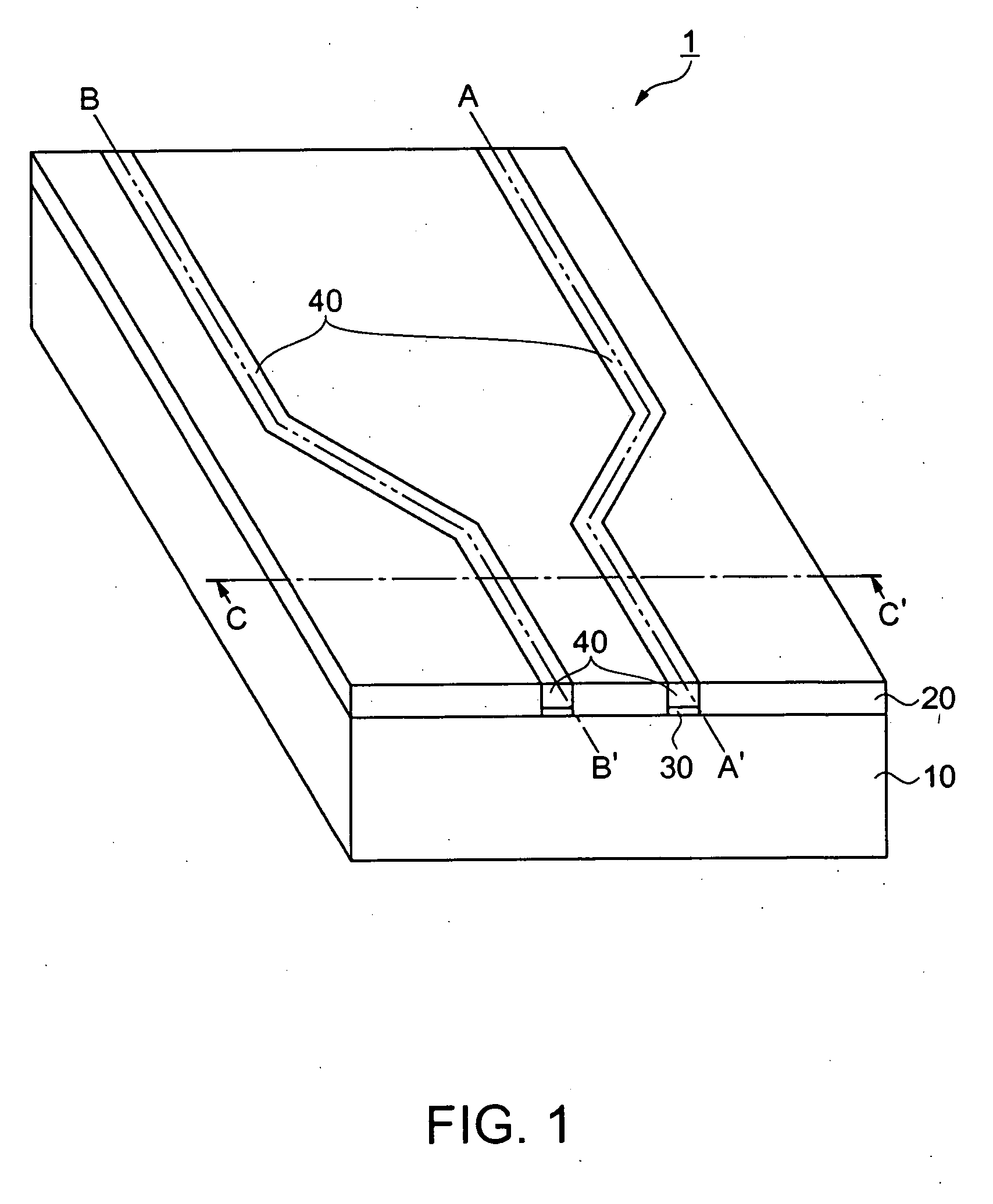
[0050]FIG. 1 is a perspective diagram of a wiring substrate 1 having electric wires formed by the electric wire formation method of the present embodiment. An X-Z plane located on a line C-C′ in FIG. 1 corresponds to a plane shown in FIG. 7B.

[0051] The wiring substrate 1 includes a support substrate 10 composed of polyimide, a bank pattern 20, a lyophilic layer 30, and a conductive layer 40. Here, both the bank pattern 20 and the lyophilic layer 30 are located on the support substrate 10. Further, the conductive layer 40 is located on the lyophilic layer 30. The bank pattern 20 is formed by processing an organic thin film composed of fluorine-containing organic molecules. More specifically, as the organic molecules, CF3CF2CF2CF2CF2CF2CF2CF2CH2CH2—Si(OCH3)3 which is a kind of a silane coupling agent is used. The bank pattern 20 containing such a material has liquid repellency against a hereinafter-described conductive material 40A (FIG. 7B). Further, the supp...

second embodiment

[0111] In the first embodiment, the lyophilic layer 30 is formed at the landing portion 50 after the bank pattern 20 is formed. In contrast, in the second embodiment, the bank pattern 20 is formed on the surface of the lyophilic layer 30 after the lyophilic layer 30 is applied to the entire surface of the support substrate 10. Except for this point, the second embodiment is basically the same as the first embodiment. Further, similarly to the foregoing descriptions, the wiring substrate 1, before being provided with the conductive layer 40, is expressed as the substrate 11.

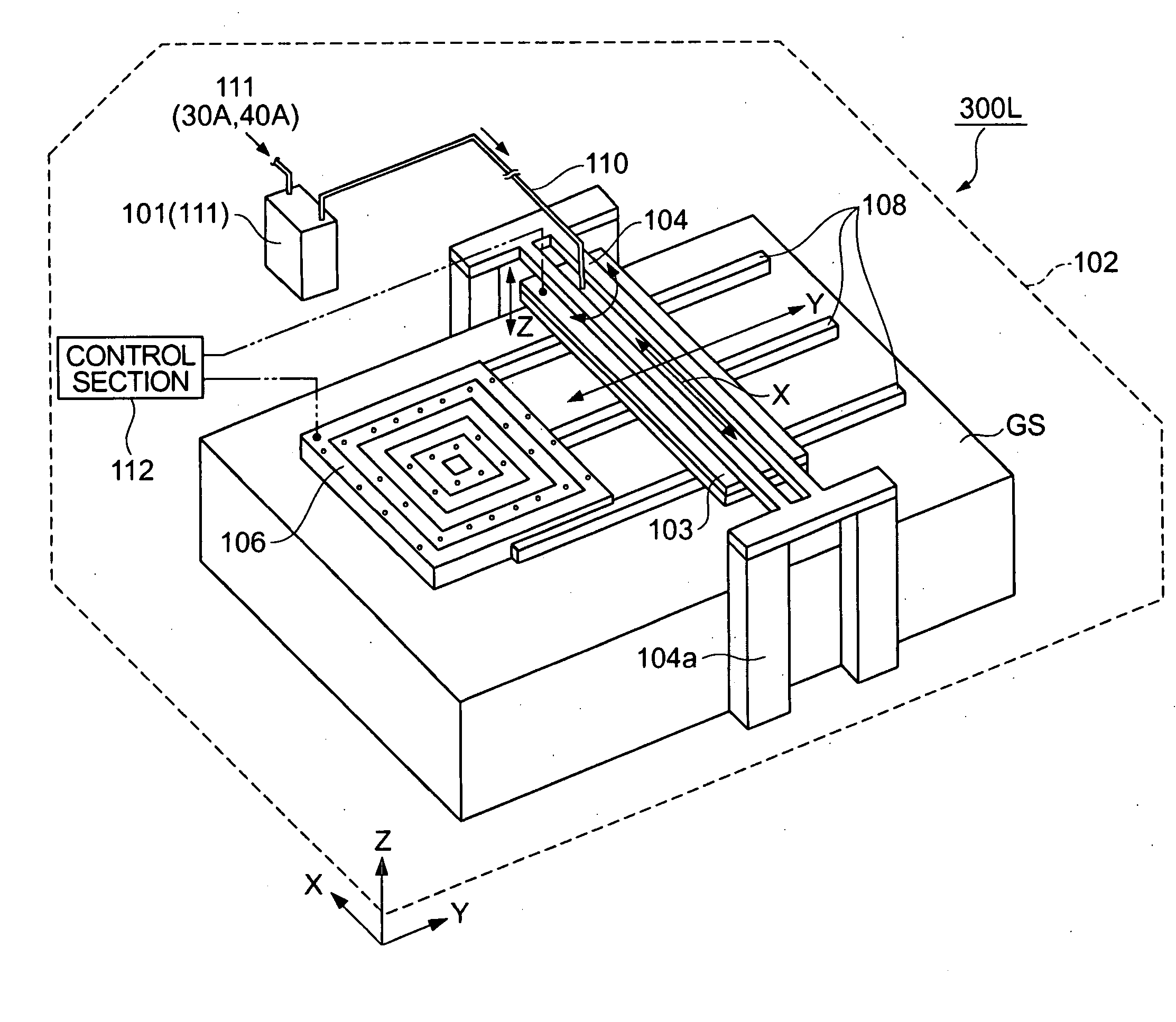
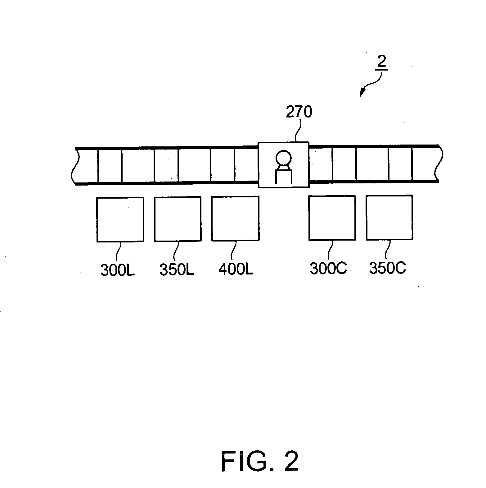
[0112] First, the UV cleaning is conducted on the support substrate 10. Then, the support substrate 10 is moved to the stage 106 of the droplet ejection apparatus 300L by the transfer apparatus 270 inside the manufacturing equipment 2. Then, the droplet ejection apparatus 300L ejects the lyophilic material 30A from the ejection part 127 of the head 114 so as to form the layer of the lyophilic material 30A on the ...

third embodiment

[0123] In the first and second embodiments, the resist layer 20B applied for the formation of the bank pattern 20 is peeled off after the patterning of the organic resin thin film 20A and the resist layer 20B. However, it is possible to manufacture the electric wires without peeling off the resist layer 20B, if the resist layer 20B itself acquires the liquid repellency against the conductive material 40A. In the following, the third embodiment using such a method will be described.

[0124] The electric wire formation method of the third embodiment is identical to the electric wire formation method of the second embodiment, except for the elements as will be described below. Therefore, descriptions of the elements similar to those in the second embodiment will be omitted.

[0125]FIGS. 13A and 13B are diagrams illustrating the electric wire formation method of the embodiment. FIG. 13A shows the substrate 11 in a state in which, after providing the substrate 11 with lyophilic layer 30, t...


PUM


Abstract

A method for forming electric wire by disposing a functional liquid by using a droplet ejection apparatus, including: forming on a substrate a partition wall defining a groove in a manner that a surface of the substrate becomes a bottom part of the groove; forming on the bottom part a lyophilic layer having a higher lyophilic property against a first functional liquid than a lyophilic property of the partition wall against the first functional liquid; and disposing on the lyophilic layer the first functional liquid containing metal by using a droplet ejection apparatus.

Description

BACKGROUND [0001] 1. Technical Field [0002] The present invention relates to an electric wire formation method and, in particular, to an electric wire formation method suitable for application of an inkjet method. [0003] 2. Related Art [0004] As a technique used for forming electric wires by an inkjet method using a droplet ejection apparatus, a technique disclosed in JP-A-2000-311527 is known. With this technique, a pattern is formed by applying ink containing an electroless plating catalyst on an ink receptive layer, and, thereafter, a conductive metal is formed on this pattern by an electroless plating method. [0005] In recent years, in order to form minuter wires, a technique has been developed, in which a partition wall called a bank pattern is formed in a manner that wires fringe a pattern to be disposed, and metal ink is applied to a groove shaped by this bank pattern and a substrate surface so as to form the electric wires. According to this technique, it is possible to form...

Claims


Application Information

Patent Timeline
Patent Type & Authority Applications(United States)
IPC IPC(8): B05D5/12
CPCH05K3/107H05K3/125H05K3/1258H05K2203/013H05K2203/0568B41J2/175
Inventor TOYODA, NAOYUKIHIRAI, TOSHIMITSU
Owner SEIKO EPSON CORP
Why Eureka
Try Eureka