Glass masking method using lasers

a laser and glass technology, applied in the field of glass windows and doors, can solve the problems of additional labor and additional opportunities, glass pane damage, and glass major surfaces may also be damaged, and achieve the effect of rapid scoring

Inactive Publication Date: 2006-06-15
LARSEN JAMES E
View PDF97 Cites 10 Cited by
  • Summary
  • Abstract
  • Description
  • Claims
  • Application Information

AI Technical Summary

Benefits of technology

[0016] The present invention thus provides a rapid method for scoring the masking material, allowing precise definition of the peripheral strip size desired. The laser beam enables forming score lines through the masking material without burning the underlying glass and underlying glass coatings. The laser device, which does not physically contact the glass or masking material, is not subject to mechanical wear and will not damage the glass surface. The frequency and power of the laser beam can be selected to adequately burn through the masking material but not the underlying glass.

Problems solved by technology

The additional glazing represented additional labor and additional opportunities for air infiltration.
There is an opportunity for damage to the glass panes at many points in the process, including the transport to the second location prior to framing, and subsequent to framing, prior to arrival at the building site.
The glass major surfaces may also be damaged after installation in the building, for example, during building construction.
This method, however, can leave polymeric material trapped along the peripheral region of the glass pane, between the glass surface and the enclosing frame member.
The visible polymeric remnants may be unsightly, and may eventually degrade and / or be pulled out, reducing the integrity of the seal between the glass surface and the enclosing window frame.
This can leave a gap between the glass surface and the window frame.
The knife blade used to cut through the polymeric material may require an undue amount of adjustment, and may not provide exactly the needed pressure to cut through the polymeric film but not into the window pane.
As windows are increasingly covered with coatings, the knife edge cutting through the outermost window coating can be very undesirable.

Method used


Image

  • Glass masking method using lasers
  • Glass masking method using lasers
  • Glass masking method using lasers

Examples


Embodiment Construction

[0032] The following detailed description should be read with reference to the drawings, in which like elements in different drawings are numbered identically. The drawings, which are not necessarily to scale, depict selected embodiments and are not intended to limit the scope of the invention. Several forms of invention have been shown and described, and other forms will now be apparent to those skilled in art. It will be understood that embodiments shown in drawings and described above are merely for illustrative purposes, and are not intended to limit scope of the invention as defined in the claims which follow.

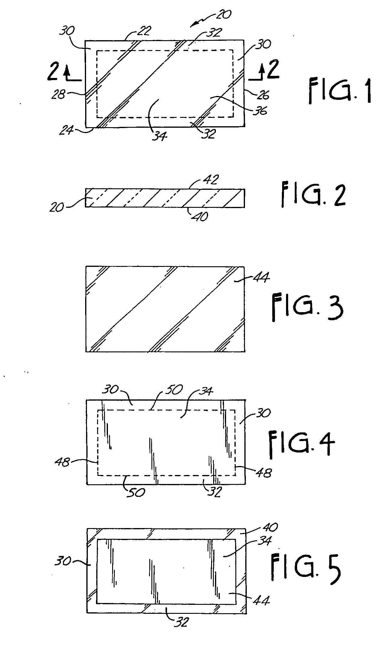
[0033] Referring now to FIG. 1, a glazing panel 20 is illustrated. Glazing panel 20 can be a single glass pane or an insulating glass unit including multiple glass panes separated by spacers. Glazing panel 20 includes generally a top edge 22, a bottom edge 24, a right side edge 26, and a left side edge 28. Glazing panel 20 includes generally a central region 34 surrounded...


PUM

PropertyMeasurementUnit
widthaaaaaaaaaa
widthaaaaaaaaaa
widthaaaaaaaaaa

Abstract

Methods and apparatus for masking glazing panels while leaving a peripheral region free of masking material. The method can include providing a masking material and applying the masking material to at least one major surface of the glazing panel. The glazing panel can be either a single glass pane or a multi-pane insulating glass unit. After application to at least one major surface, a laser can be used to describe a closed path on the major surface, thereby cutting or scoring the masking material through to the glass major surface. The path demarcates a central, masked region from a peripheral masked region of the glazing panel. In one method, the laser cuts a muntin bar pattern having several central regions. The laser power can be selected and / or adjusted such that the masking material is burned through, without damage to the underlying glass material and any coatings on the glass material. After cutting through the masking material to define the peripheral masked region, the peripheral masked region can be peeled or stripped off from the masked glazing panel. The remaining panel thus has a protective mask about the central region while leaving the peripheral region unprotected. The resultant masked glazing panel may be assembled into a window unit by mounting window frame members about the four sides of the glazing panel. The window frame members may thus have a tight and durable fit directly to the glass in the peripheral region, while the central region of the glazing panel remains protected by the masking material.

Description

BACKGROUND OF INVENTION [0001] 1. Field of the Invention [0002] The present invention relates generally to glass windows and doors. More specifically, the present invention relates to preparing glass panels for insertion into window frames. The present invention includes methods for protecting or masking glass panes to be disposed within window frames, while leaving the peripheral region free to be better sealed within a frame. [0003] 2. Description of Related Art [0004] Glazing panels are often mounted within frames such as window frames. The glazing panels can be single glass panes or multi-pane, insulating glass units. The window panes typically have first and second major surfaces with peripheral edges about the major surfaces, and peripheral regions within the peripheral edges. The peripheral regions bound a central region on each of the first and second major surfaces. The glass panes are typically ultimately disposed within frames, where the frames are dimensional and configu...

Claims


Application Information

Patent Timeline
Patent Type & Authority Applications(United States)
IPC IPC(8): E06B3/24B23K26/06B29C63/00B29C63/02B32B17/10B32B27/36B32B37/22C03C23/00E06B3/68
CPCB23K26/0661Y10T156/108B29C63/02B29C2793/009B29L2031/7782B32B17/10018B32B27/36B32B37/226B32B38/105B32B2310/0843B32B2315/08C03C23/0025C03C2218/34E06B3/685Y10T156/1052B29C63/0056
Inventor LARSEN, JAMES E.
Owner LARSEN JAMES E
Why Eureka
Try Eureka