Wafer bonded MOS decoupling capacitor

a technology of mos capacitor and mos, which is applied in the direction of semiconductor devices, semiconductor/solid-state device details, electrical apparatus, etc., can solve the problems of increasing the cost of packaging, increasing the cost of mos capacitor fabrication, and increasing the parasitic inductan

Active Publication Date: 2006-06-15
TEXAS INSTR INC
View PDF6 Cites 27 Cited by
  • Summary
  • Abstract
  • Description
  • Claims
  • Application Information

AI Technical Summary

Benefits of technology

[0005] The following presents a simplified summary of the invention in order to provide a basic understanding of some aspects of the invention. This summary is not an extensive overview of the invention. It is intended neither to identify key or critical elements of the invention nor to delineate the scope of the invention. Rather, its primary purpose is merely to present one or more concepts of the invention in a simplified form as a prelude to the more detailed description that is presented later.
[0006] The present invention relates to forming a MOS capacitor in a cost effective manner that allows the capacitor to be operatively coupled to a portion of an integrated circuit so that the capacitor can serve as a decoupling capacitor. According to one or more aspects of the present invention, a method of forming a MOS decoupling capacitor includes patterning a layer of capacitor top electrode material that is formed over a layer of capacitor dielectric material and patterning the layer of capacitor dielectric material which is formed over a semiconductor substrate. A layer of dielectric material is formed over the substrate and the patterned layers of capacitor top electrode and dielectric materials. Vias are then formed within the layer of dielectric material down to the patterned layer of capacitor top electrode material and also down to the substrate. At least one deep contact via that penetrates into the substrate is also formed within the layer of dielectric material. The vias are filled with a conductive material, and a first metallization layer is formed over the layer of dielectric material and the filled vias. The first metallization layer is patterned to form conductive contact pads over the filled vias, and the capacitor is then aligned with an integrated circuit device such that the contact pads of the capacitor are aligned with contact pads of the integrated circuit device. An anneal is performed to fuse the contact pads of the capacitor and the contact pads of the integrated circuit device. Some of the substrate is then removed to expose the at least one deep contact via, and a second metallization layer is formed over the substrate and the at least one deep contact via. The second metallization layer is then patterned to form respective bond pads over the at least one deep contact via.

Problems solved by technology

Additionally, this parasitic inductance generally increases as the decoupling capacitor is moved away from the IC.
Although desirable, it is costly to fabricate MOS capacitors as part of ICs since doing so lengthens and complicates fabrication processes and consumes valuable semiconductor real estate, among other things, for example.
This, however, increases the cost of packaging and moves the capacitors away from the IC, exacerbating adverse effects associated with parasitic inductance.

Method used


Image

  • Wafer bonded MOS decoupling capacitor
  • Wafer bonded MOS decoupling capacitor
  • Wafer bonded MOS decoupling capacitor

Examples


Embodiment Construction

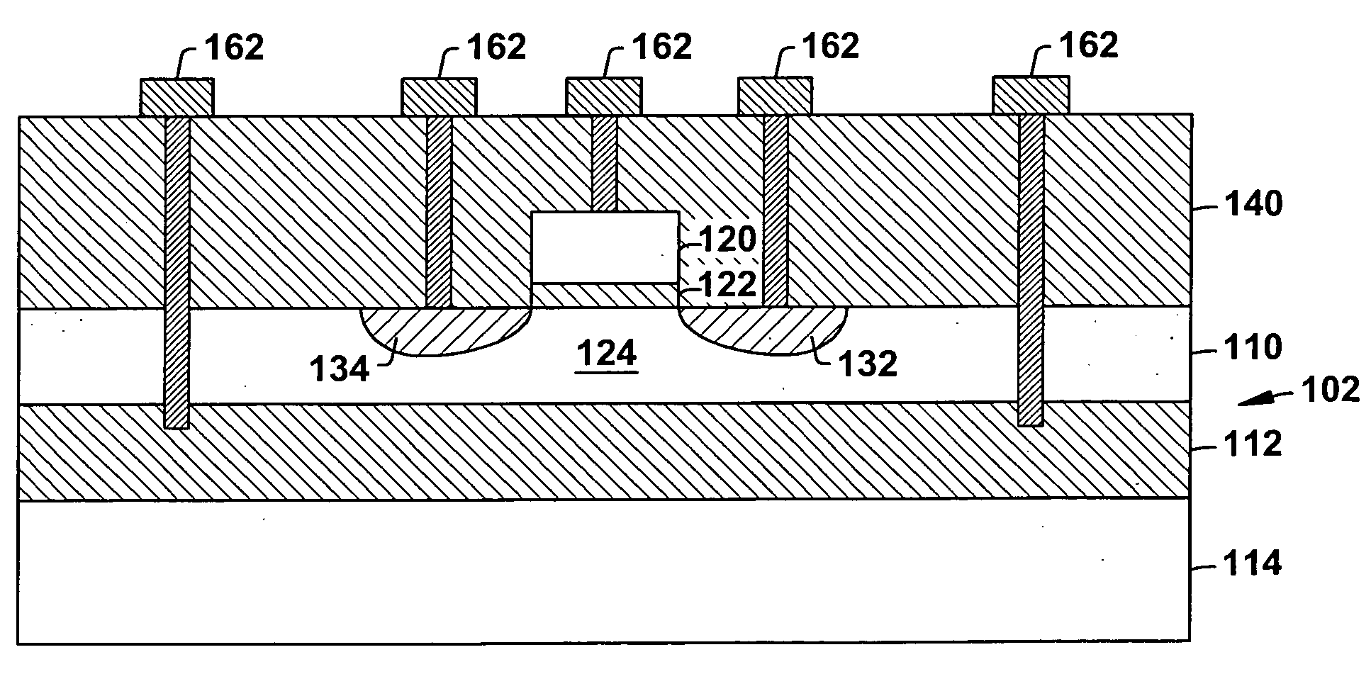
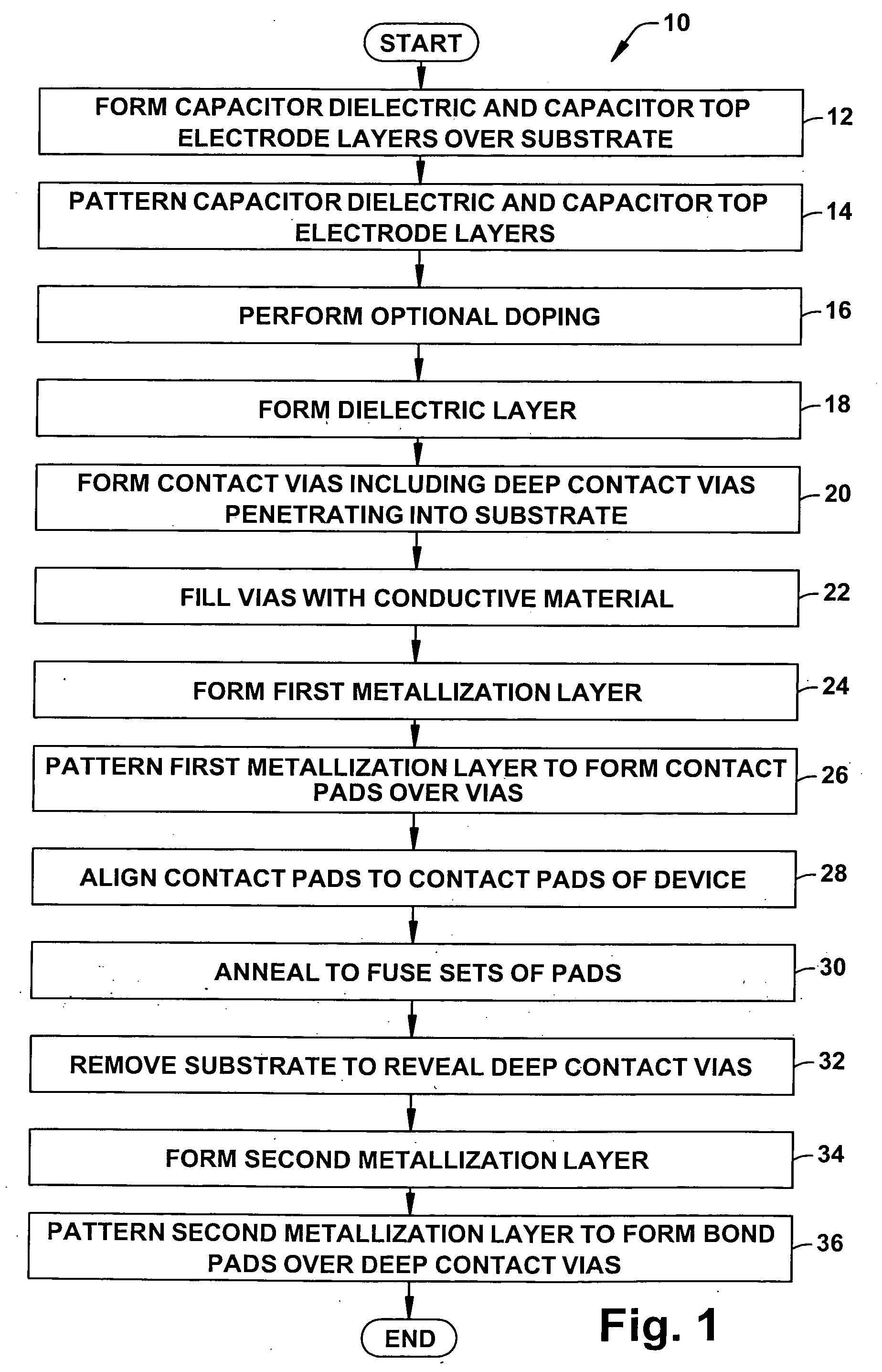
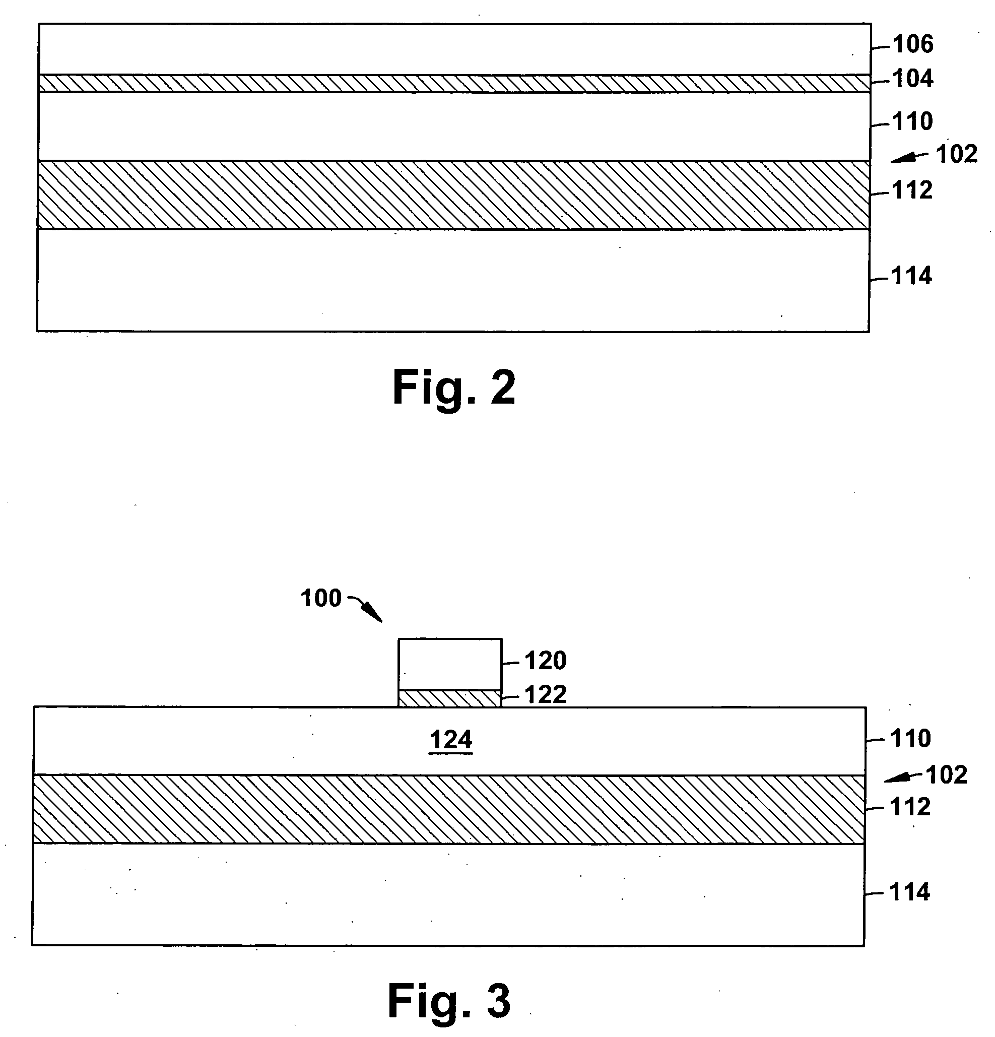
[0010] One or more aspects of the present invention are described with reference to the drawings, wherein like reference numerals are generally utilized to refer to like elements throughout, and wherein the various structures are not necessarily drawn to scale. It will be appreciated that where like acts, events, elements, layers, structures, etc. are reproduced, subsequent (redundant) discussions of the same may be omitted for the sake of brevity. In the following description, for purposes of explanation, numerous specific details are set forth in order to provide a thorough understanding of one or more aspects of the present invention. It may be evident, however, to one of ordinary skill in the art that one or more aspects of the present invention may be practiced with a lesser degree of these specific details. In other instances, known structures are shown in diagrammatic form in order to facilitate describing one or more aspects of the present invention.

[0011] The present inven...


PUM


Abstract

A technique for forming a MOS capacitor (100) that can be utilized as a decoupling capacitor is disclosed. The MOS capacitor (100) is formed separately from the particular circuit device (170) that it is to service. As such, the capacitor (100) and its fabrication process can be optimized in terms of efficiency, etc. The capacitor (100) is fabricated with conductive contacts (162) that allow it to be fused to the device (170) via conductive pads (172) of the device (170). As such, the capacitor (100) and device (170) can be packaged together and valuable semiconductor real estate can be conserved as the capacitor (100) is not formed out of the same substrate as the device (170). The capacitor (100) further includes deep contacts (150, 152) whereon bond pads (180, 182) can be formed that allow electrical connection of the capacitor (100) and device (170) to the outside world.

Description

FIELD OF INVENTION [0001] The present invention relates generally to semiconductor devices, and more particularly to fashioning a metal oxide semiconductor (MOS) capacitor that can be operatively coupled to an integrated circuit to serve as a decoupling capacitor. BACKGROUND OF THE INVENTION [0002] Capacitors, such as metal oxide semiconductor (MOS) capacitors, are often associated with integrated circuits (ICs) to facilitate the provision of a steady supply of current to one or more parts of the circuit. Capacitors provide a steady supply of current to ICs and mitigate transient currents by, among other things, acting as a charge reservoir that steadily discharges stored current regardless of the transients that the circuit, or parts thereof, are exposed to, such as power to ground noise, for example. Since such capacitors separate or decouple one or more parts of the IC from surrounding noise, they are often referred to as decoupling capacitors. [0003] It can be appreciated that i...

Claims


Application Information

Patent Timeline
Patent Type & Authority Applications(United States)
IPC IPC(8): H01L21/20H01L21/8242
CPCH01L23/481H01L23/50H01L29/66189H01L29/94H01L2924/0002H01L2924/00H01L27/04H10B12/00
Inventor ROUSE, RICHARD P.
Owner TEXAS INSTR INC
Why Eureka
Try Eureka