Cooling arrangement for a humanoid robot

a technology for humanoids and cooling arrangements, which is applied in the field of cooling arrangements for humanoids, can solve the problems of significant pressure drop of air flow, insufficient natural ventilation to control the inner temperature of robots, and less effective cooling of the central back part of inner components, so as to achieve effective and uniform cooling, reduce power consumption and reduce noise. the effect of emitted

a technology for humanoids and cooling arrangements, which is applied in the field of cooling arrangements for humanoids, can solve the problems of significant pressure drop of air flow, insufficient natural ventilation to control the inner temperature of robots, and less effective cooling of the central back part of inner components, so as to achieve effective and uniform cooling, reduce power consumption and reduce noise. the effect of emitted

US20060128261A1Inactive Publication Date: 2006-06-15HONDA MOTOR CO LTD

Image

  • Cooling arrangement for a humanoid robot
  • Cooling arrangement for a humanoid robot
  • Cooling arrangement for a humanoid robot

Examples


Embodiment Construction

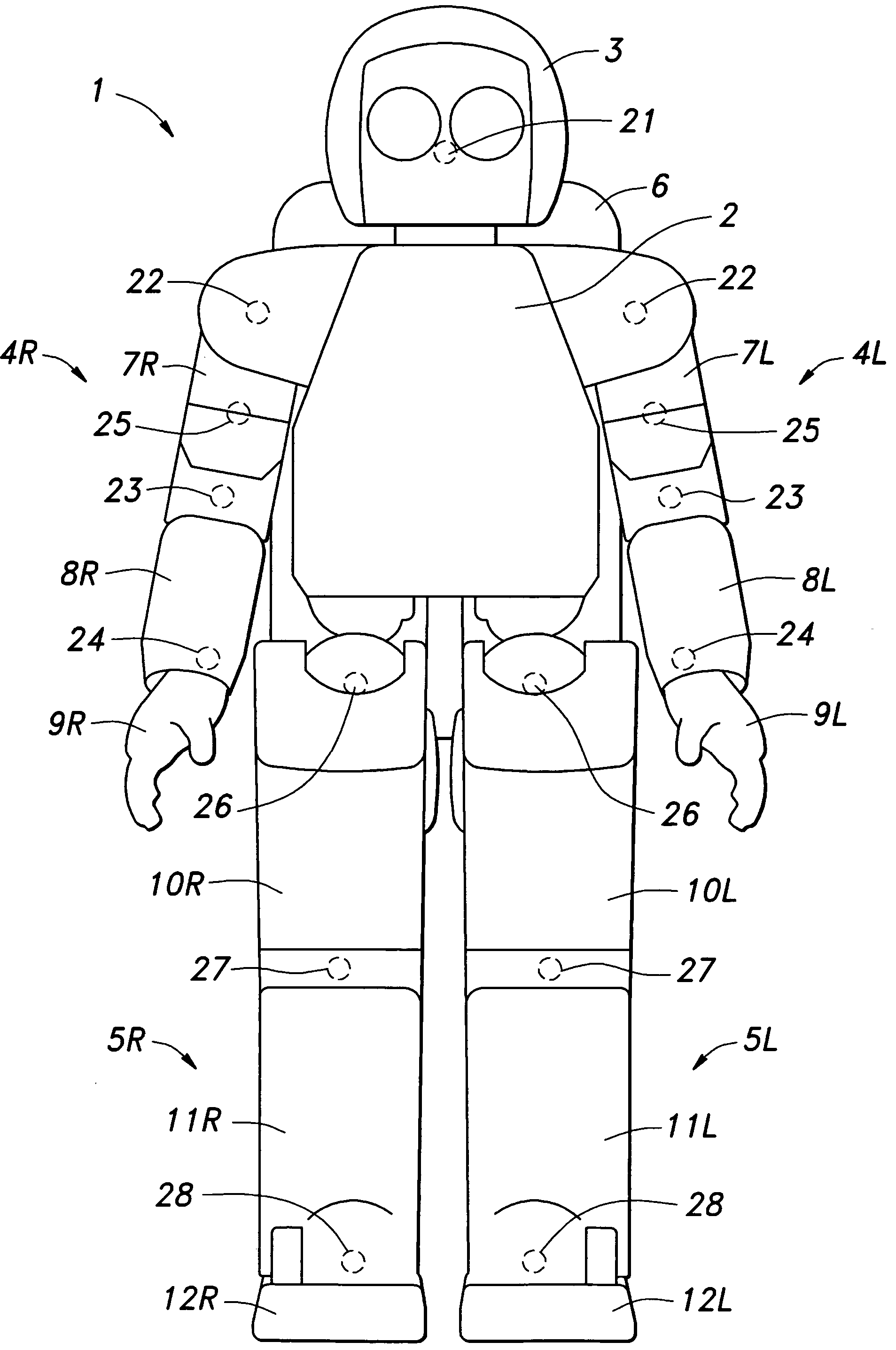
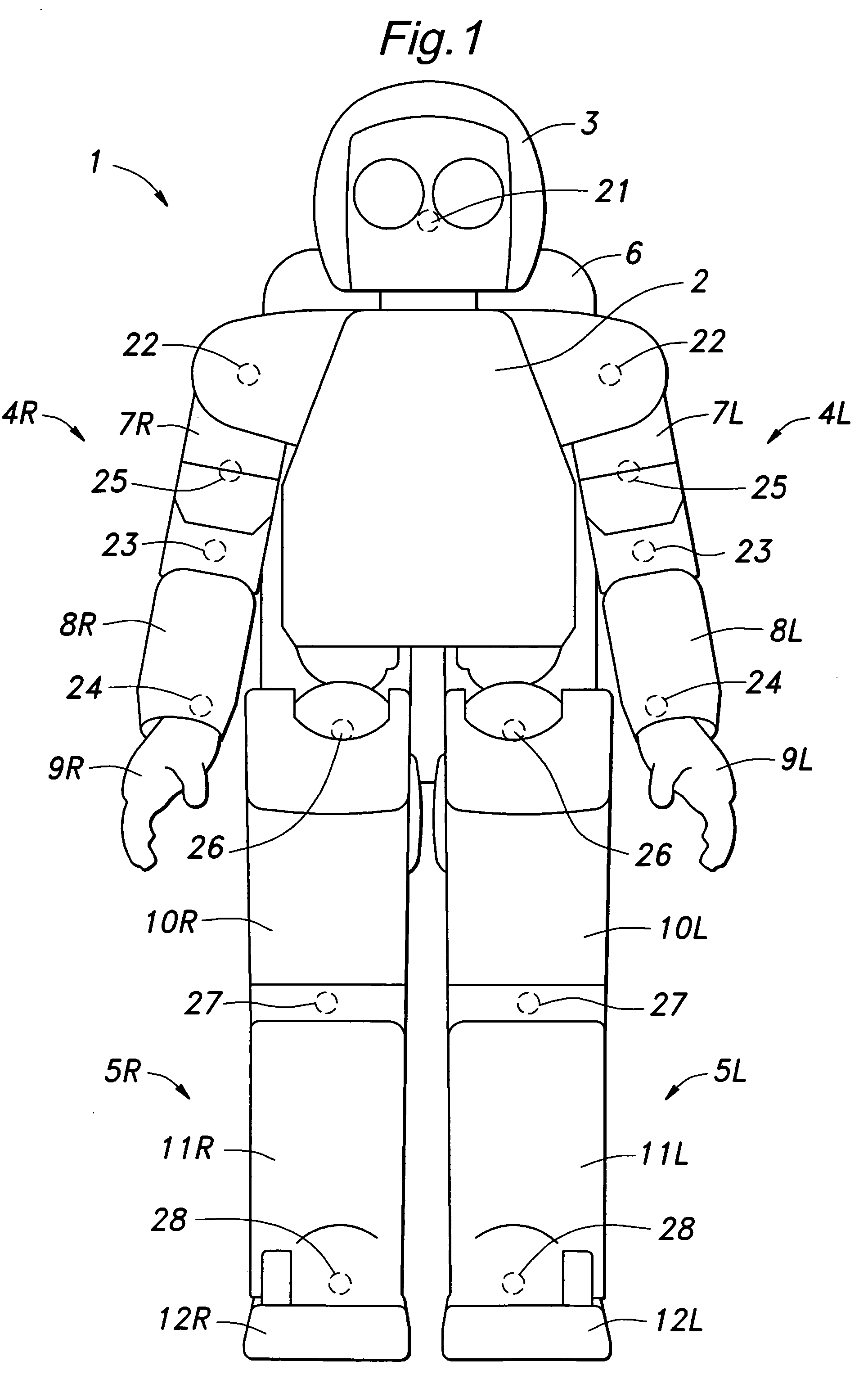
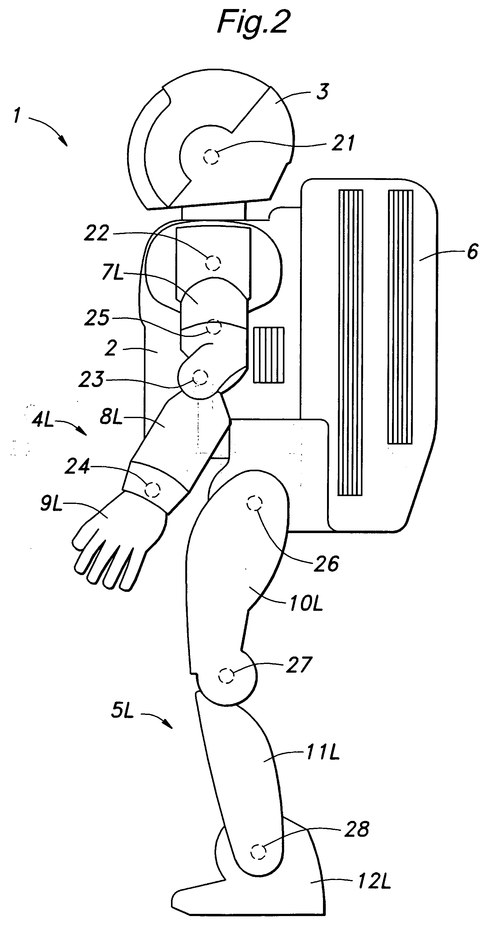
[0020] Referring to FIGS. 1 and 2;, the humanoid robot 1 (which is referred to simply as a robot hereinafter) embodying the present invention comprises a torso 2, a head 3, a pair of arms 4L and 4R, a pair of legs 5L and 5R and a backpack box 6. Each arm 4L (4R) includes an upper arm 7L (7R), a lower arm 8L (8R) and a hand 9L (9R). Likewise, each leg includes an upper leg 10L (10R), a lower leg 11L (11R) and a foot 12L (12R).

[0021] The head 3 is connected to the torso 2 via a neck joint 21. Each upper arm 7L (7R) is connected to the torso 2 via a shoulder joint 22 at an upper end thereof and connected to the corresponding lower arm 8L (8R) via an elbow joint 23 at a lower end thereof. The lower arm 8L (8R) is in turn connected to the corresponding hand 9L (9R) via a wrist joint 24. A middle part of each upper arm 7L (7R) is provided with an upper arm joint 25 so that the upper and lower parts of the upper arm can be rotated relative to each other around an axial line extending cent...


PUM


Abstract

A torso part (2) and a backpack part (6) of a humanoid robot are commonly formed by a shell that defines an inner space that accommodates a heat generating component such as a control computer (31) and a power module (32, 33). The shell comprises an air vent hole (45, 46) provided on one lateral side of the shell, an air inlet hole (47, 48) provided on the other lateral side of the shell and a powered fan (49) provided immediately inside the air vent hole. Because the cooling air can flow laterally across the inner space, the entire part of the heat generating component can contact the air flow, and a uniform cooling effect can be achieved with a minimum power consumption and a minimum noise generation.

Description

TECHNICAL FIELD [0001] The present invention relates to a cooling arrangement for a humanoid robot having heat generating components such as a control computer and a power module inside a shell that forms at least a torso part of the robot, and in particular to a cooling arrangement for a humanoid robot that can improve the cooling efficiency. BACKGROUND OF THE INVENTION [0002] Various forms of humanoid robots have been developed. Unlike stationary industrial robots that are employed in painting, welding, assembling and other manufacturing work, a humanoid robot is required to be more compact because of the need to move about in a limited space with a limited power resource. A typical humanoid robot includes a battery, a control computer and a power module for the purpose actuating various drive motors for moving the arms and legs thereof in a highly coordinated fashion, and such components are typically accommodated in the torso part of the robot as there is no other available spac...

Claims


Application Information

Patent Timeline
15 Jun 2006
Publication
US20060128261A1
IPC
A63H3/00
CPC
B25J19/0054
Inventors
KAWABE, KOJI; KOYANAGI, TAKURO