
Method and apparatus for operating an injection system in an internal combustion engine

Inactive Publication Date: 2006-06-15
ROBERT BOSCH GMBH
View PDF5 Cites 2 Cited by
  • Summary
  • Abstract
  • Description
  • Claims
  • Application Information

AI Technical Summary

Benefits of technology

[0009] It is an object of the present invention to improve a method and an apparatus of the kind cited initially in such a way that by adaptation of the triggering voltage of injection actuators, e.g., piezoactuators, of an injection system, the quantitative accuracy with which fuel is metered is, in particular, enhanced even during operation of the internal combustion engine or of an underlying motor vehicle.
[0014] A further advantage is the fact that the triggering voltage can be adapted, without additional sensor outlay, to changing operating conditions of the internal combustion engine, in particular to changing state variables of the injection system, the result being even more precise fuel monitoring as compared with conventional systems.

Problems solved by technology

It is therefore not possible to improve the accuracy of the injected quantities even further during operation.
This is disadvantageous specifically with regard to emissions standards that must be met in the future.
Production- and aging-related variations in the fuel quantity injected into the individual combustion chambers cause different fuel quantities to be delivered for the same triggering signal, resulting, in particular with very small quantities injected in preinjection operations, in considerable quantity errors.
If the injection actuator has a lower voltage applied to it, however, the force generated thereby is not sufficient to open the control valve against the rail pressure.
In other words, a sharp separation exists with regard to the system reaction in terms of insufficient / sufficient triggering voltage.

Method used


Image

  • Method and apparatus for operating an injection system in an internal combustion engine
  • Method and apparatus for operating an injection system in an internal combustion engine
  • Method and apparatus for operating an injection system in an internal combustion engine

Examples


Embodiment Construction

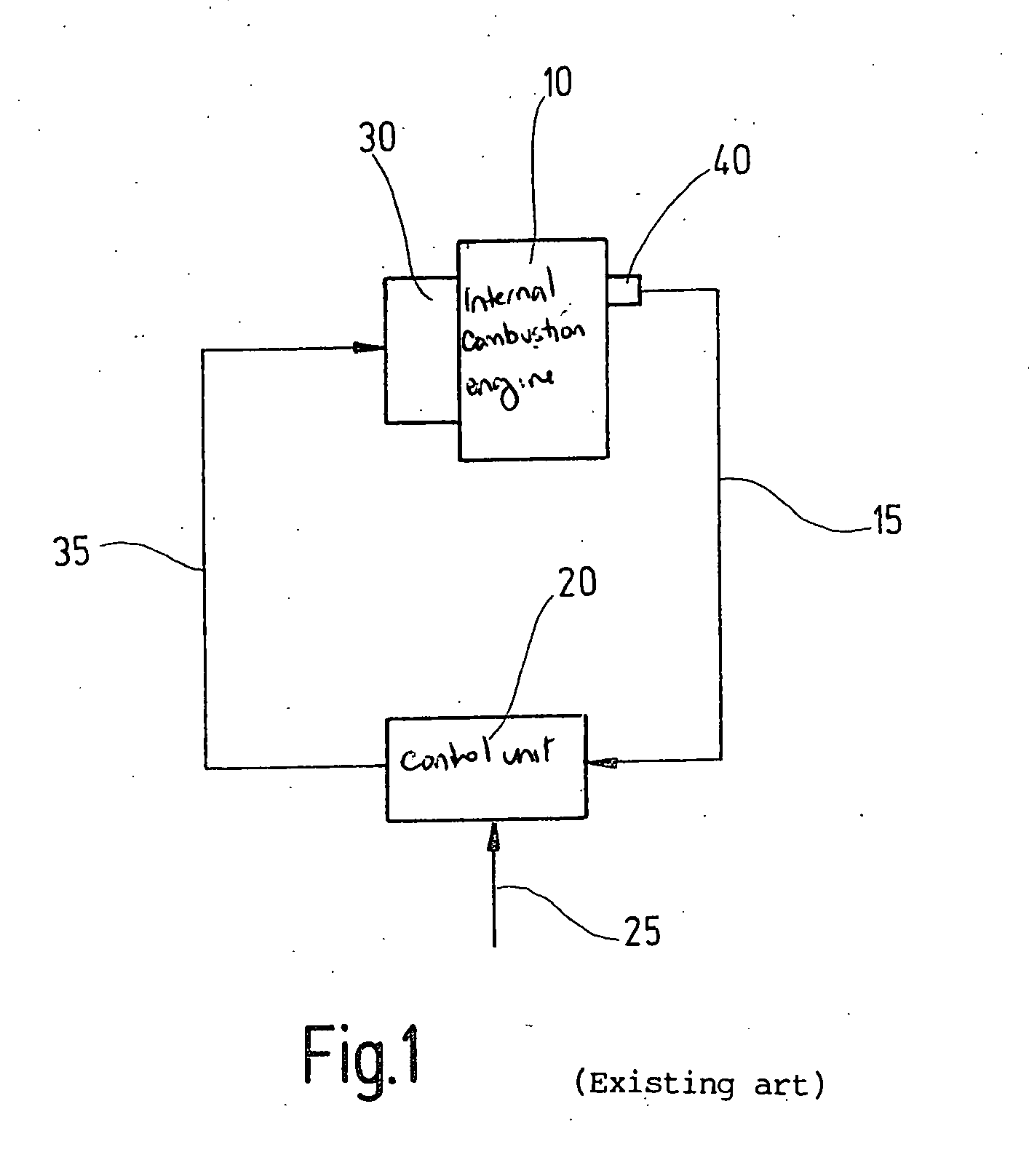
[0023]FIG. 1 schematically shows the construction of a fuel injection system of a compression-ignited internal combustion engine described in, for example, German Patent No. DE 39 29 747 A1. Internal combustion engine 10, depicted here only schematically, receives a specific fuel quantity metered to it by an injection unit 30. The instantaneous operating state of internal combustion engine 10 is sensed by means of sensors 40, and measured values 15 thus sensed are transferred to a control unit 20. These measured values encompass, for example, the rotation speed and temperature of the internal combustion engine, as well as the actual injection onset and possibly also other variables 25 that characterize the operating state of the internal combustion engine, for example the position of an accelerator pedal 25 or the ambient atmospheric pressure. On the basis of measured values 15 and further variables 25, control unit 35 calculates triggering pulses 35 in accordance with the fuel quan...


PUM


Abstract

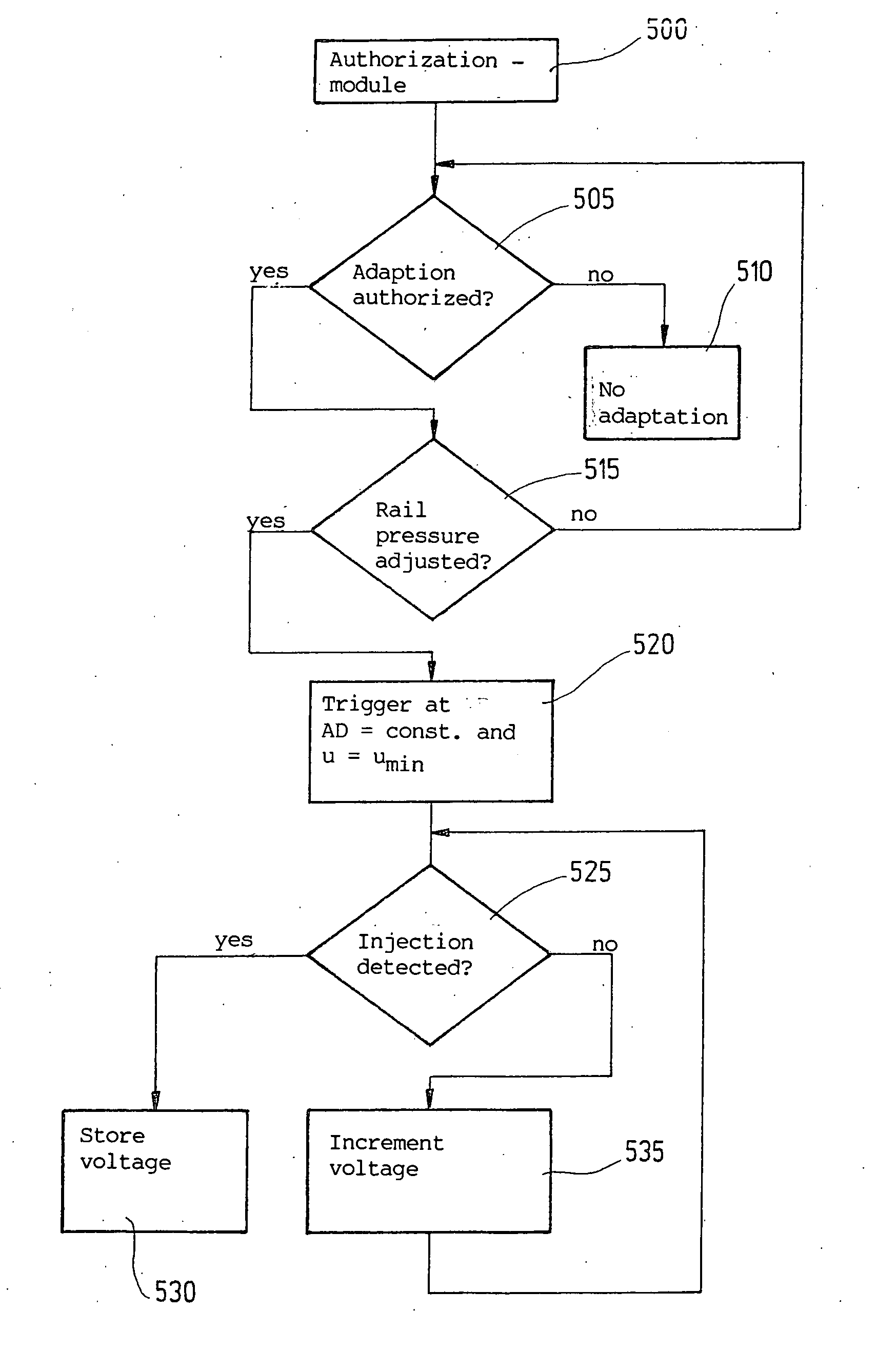
In a method and an apparatus for operating an injection system of an internal combustion engine, triggering of an injection actuator being performed on the basis of at least one state variable of the injection system, in order to enhance the quantitative accuracy with which fuel is metered provision is made that the at least one state variable is sensed and temporarily stored; the at least one injection actuator is triggered with a triggering pulse of definable pulse duration and definable initial pulse height; during the triggering of the at least one injection actuator, an injection detection is performed; the pulse height of the triggering pulse is incremented in definable steps, at the defined pulse duration, until an injection is detected; and when an injection is detected, the pulse height of the triggering pulse causing the injection is permanently stored as a function of the sensed state variable, and in future operation of the injection system is taken as the basis for triggering the at least one injection actuator.

Description

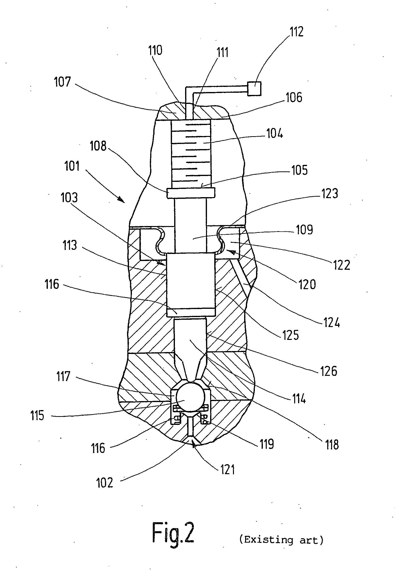
FIELD OF THE INVENTION [0001] The invention relates to a method and an apparatus for operating an injection system of an internal combustion engine. BACKGROUND INFORMATION [0002] A high-pressure injection, and an injection valve (injector) equipped with a piezoactuator as the injection actuator, are described in German Patent Application Nos. DE 100 32 022 A1 and DE 100 02 270 C1. An injection valve of this kind serves for precisely regulatable fuel metering into the combustion chamber of the internal combustion engine. [0003] In an injection valve of this kind, the piezoactuator serves to control the motion of a nozzle needle of the injection valve, either the nozzle needle itself or a control valve controlling the motion of the nozzle needle being triggered. [0004] For exact metering of fuel into the combustion chamber, the most accurate possible knowledge of the stroke length of the piezoactuator or nozzle needle, in interaction with the control valve, is necessary. As is evident...

Claims


Application Information

Patent Timeline
IPC IPC(8): F02D41/30F02D35/02F02D41/12F02D41/14F02D41/20F02D41/24
CPCF02D35/021F02D35/023F02D35/027F02D41/123F02D41/2096F02D41/2438F02D41/247F02D2041/2055
Inventor RUEGER, JOHANNES-JOERGSCHULZ, UDO
Owner ROBERT BOSCH GMBH
Learn More