Air filter system

Active Publication Date: 2006-06-22
MANN HUMMEL GMBH
View PDF15 Cites 11 Cited by
  • Summary
  • Abstract
  • Description
  • Claims
  • Application Information

AI Technical Summary

Benefits of technology

[0007] A further object is to provide an air filter system which can be disposed in the intake tract of an internal combustion engine and which further reduces pollutant emissions.
[000

Problems solved by technology

However, the drawback in connection with the aforementioned SULEV/ULEV problem is that any hydrocarbons present in the

Method used


Image

  • Air filter system
  • Air filter system
  • Air filter system

Examples


Embodiment Construction

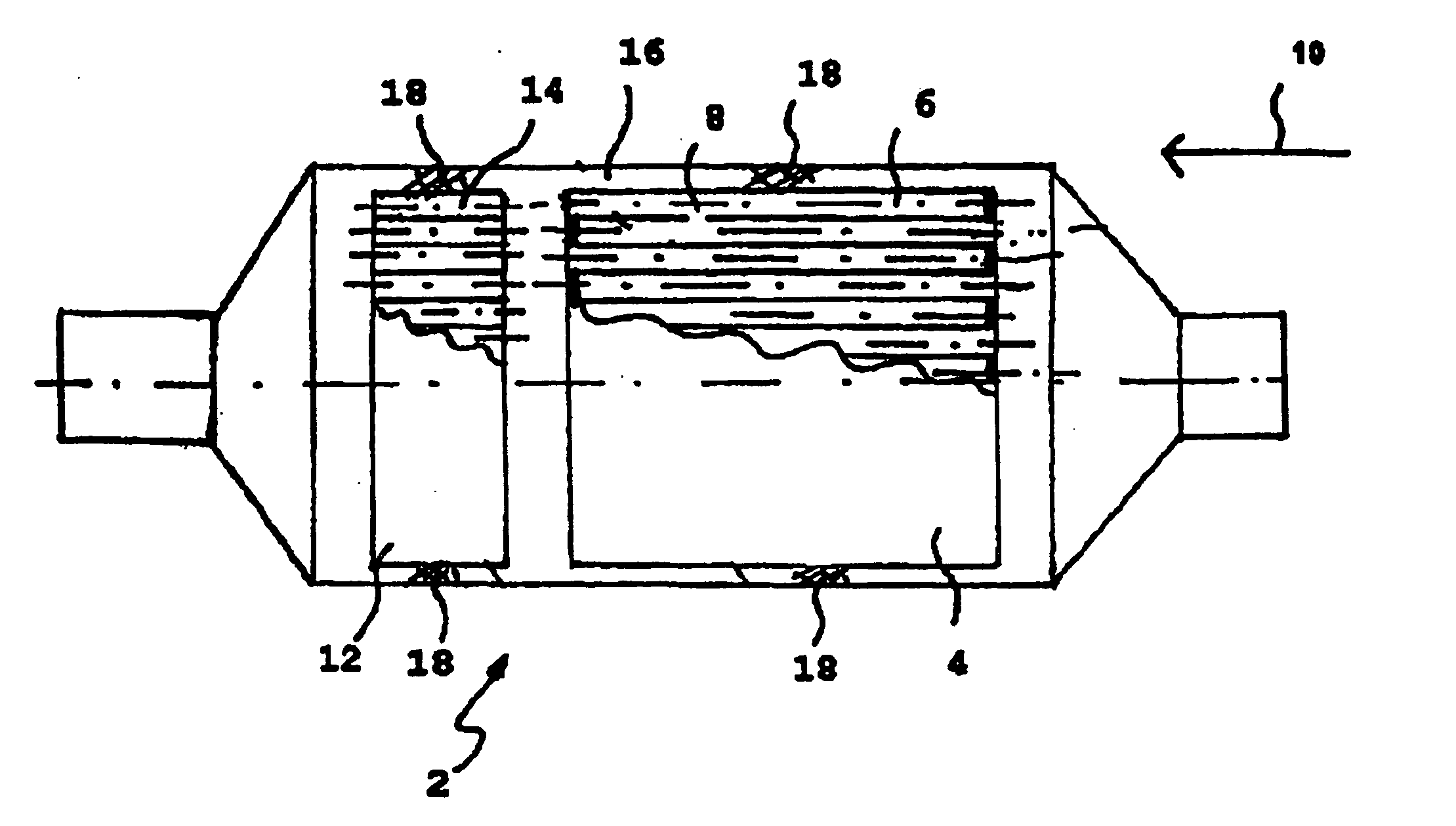
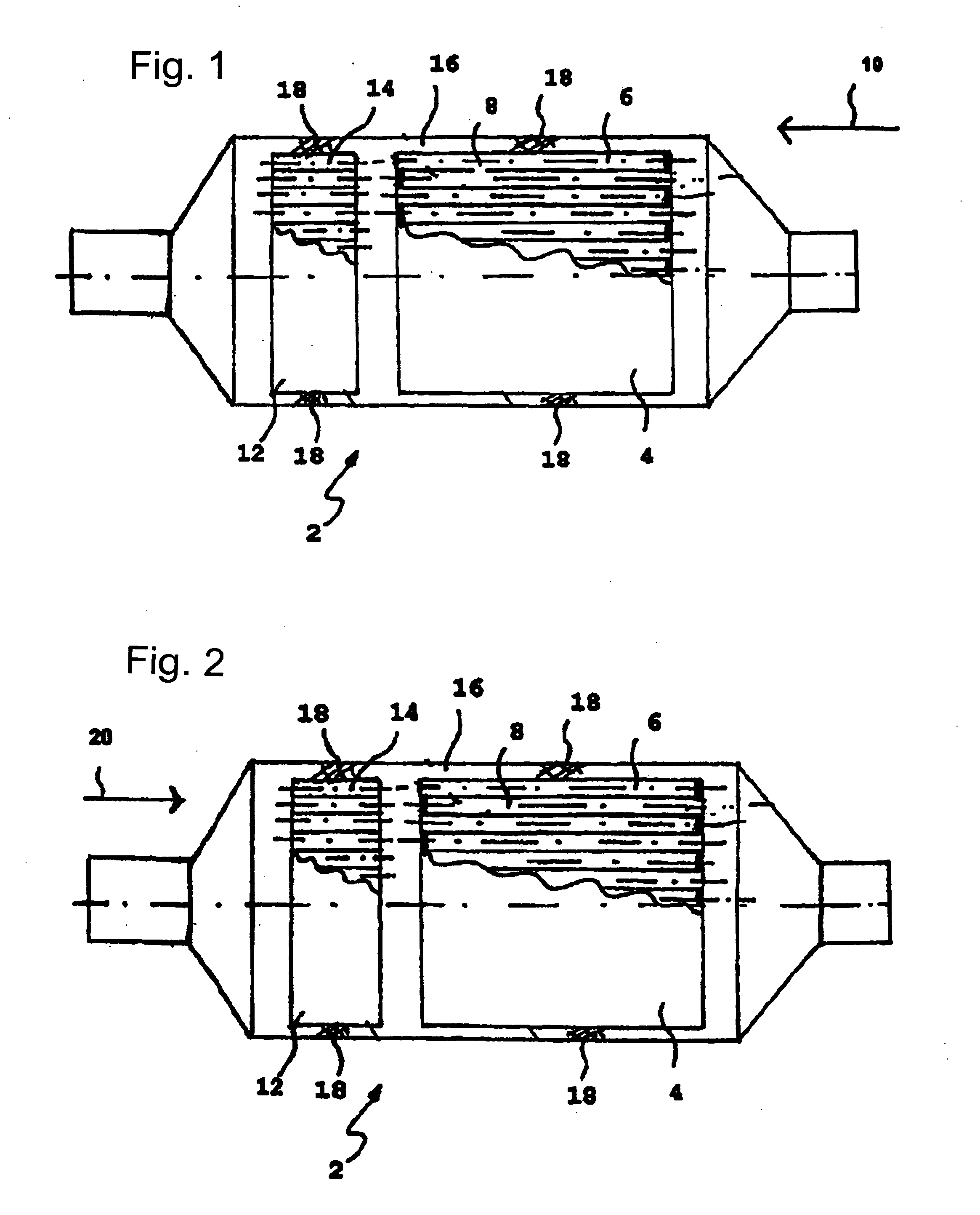
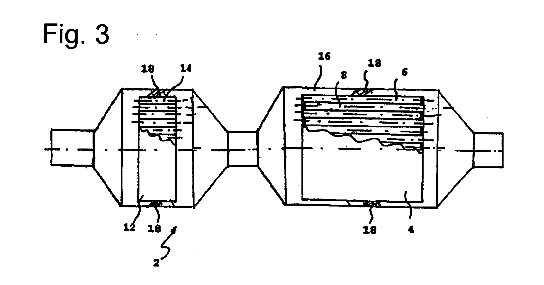
[0015]FIG. 1 is a schematic representation of an embodiment of the air filter system according to the invention showing the flow direction of the intake air through the air filter system. FIG. 2 is a schematic representation of an embodiment of the air filter system according to the invention showing the flow direction of the hydrocarbon vapors when the engine and / or vehicle is stopped.

[0016] As can be seen in FIG. 1, the air filter system 2 has a filter element 4 for end-face inflow, which has inflow and outflow-side channels 6, 8 that are alternately sealed. They can be sealed, for example, by an adhesive, particularly a hot-setting adhesive or hot-melt adhesive, before the filter is wound, i.e., in an amount just sufficient to seal the channels and at the same time glue the winding. The fluid to be filtered flows from the inflow face in the direction of arrow 10 into the channels 6 of the filter element 4 open on the inflow face and out of the filter element 4 in the same direct...


PUM

PropertyMeasurementUnit
Flow rateaaaaaaaaaa
Structureaaaaaaaaaa

Abstract

An air filter system with an air filter element having an inflow and an outflow face and comprising alternating flat and pleated layers, which are configured to form channels. The channels are alternately sealed in inflow and outflow direction, such that the medium to be filtered must pass through one of the layers as it flows from the inflow face through the filter to the outflow face. An adsorber element made of an activated carbon coated honeycomb structure is disposed adjacent the air filter element.

Description

BACKGROUND OF THE INVENTION [0001] The present invention relates to an air filter system comprising an air filter element having an inflow face and an outflow face and comprising alternating flat and pleated layers which form alternately sealed channels, and particularly to an air filter system of the foregoing type for use with an internal combustion engine. [0002] An essential development goal in modern internal combustion engines is to reduce emission of harmful substances. Until now, the development activities focused primarily on optimizing the exhaust emission control system. Modern exhaust emission control systems meanwhile achieve conversion rates for harmful substances greater than 97%. Increasing air pollution has led most countries to limit emissions and to continue to tighten these limits. To assure reproducibility and comparability, various test methods, ratings and limits have been developed. In the United States, for example, the limits include the category ULEV (Ultr...

Claims


Application Information

Patent Timeline
IPC IPC(8): B01D53/02
CPCB01D46/0036B01D46/2422B01D2253/102
Inventor DURST, MICHAELMOSER, NIKOLAUSPELZ, ANDREASWEBER, OLAF
Owner MANN HUMMEL GMBH
Why Eureka
Try Eureka