Retort basket securing system

Active Publication Date: 2006-06-22
ALLPAX PRODS
View PDF6 Cites 8 Cited by
  • Summary
  • Abstract
  • Description
  • Claims
  • Application Information

AI Technical Summary

Benefits of technology

[0020] In the preferred embodiment, the present bladder-actuated devices lift the filled basket vertically to clamp the basket to an opposing fixed platen, to eliminate movement on one axis, and two separate bladder-actuated systems engage the basket horizontally against an opposing fixed platen, to eliminate movement on the other axis lateral to the first.
[0021] Custom machined fittings at each end of each bladder allow air pressure to be quickly and efficiently supplied to the system, and spring bias means and a pressure rail situated along the length of each of the the upper and lower platens sandwiching

Problems solved by technology

Even a small movement between the basket and the retort (or rotational insert where one is used) results in continuous wear and tear on the basket and retort, strain on the drive system due to inconsistent forces associated with the movement of the basket(s) (each loaded basket can weigh in excess of 4000 lbs), and potential damage to the product situated within the baskets.
However, such mechanical configurations are expensive to provide and maintain, and are prone to breakage due to the extreme operating environment caused by high temperatures under pressurized conditions, high operating cycles and high weights associated with the stack.
Further, the nature of the actuator requires that it be fabricated of expensive materials due to the extreme operating environment.
Further, the prior art actuators are required to be operable on a rotating mechanism, which further complicates its desig

Method used


Image

  • Retort basket securing system
  • Retort basket securing system
  • Retort basket securing system

Examples


Example

DETAILED DISCUSSION OF THE INVENTION

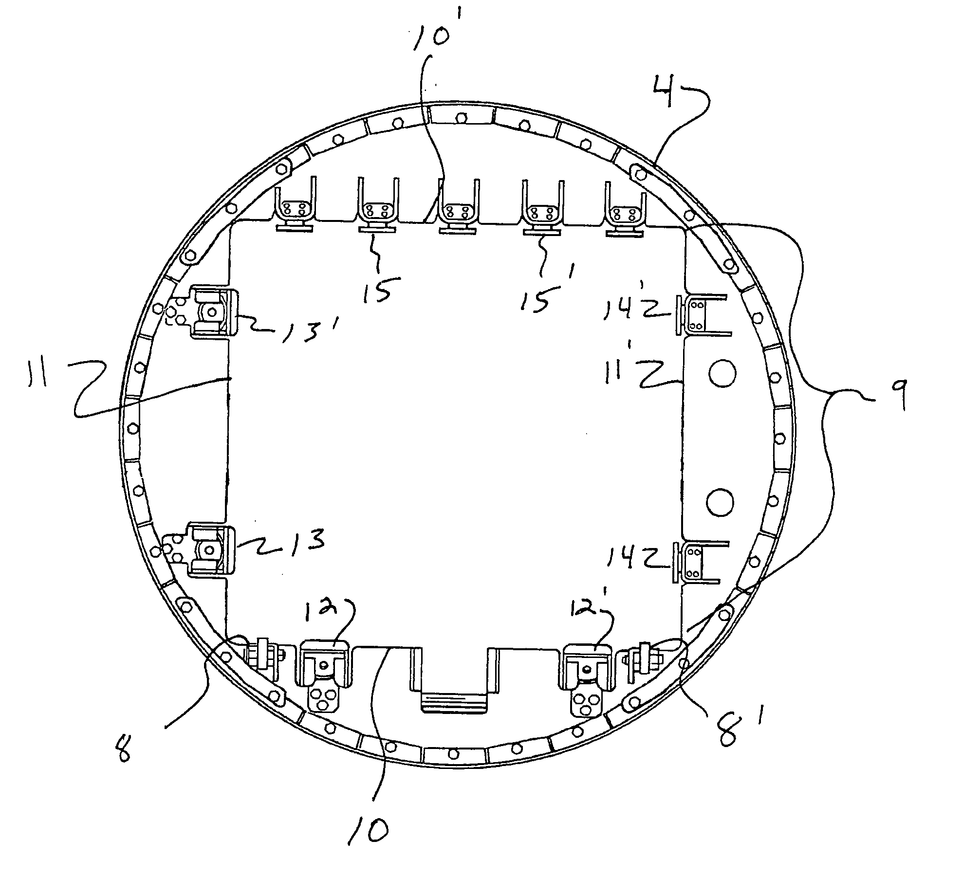
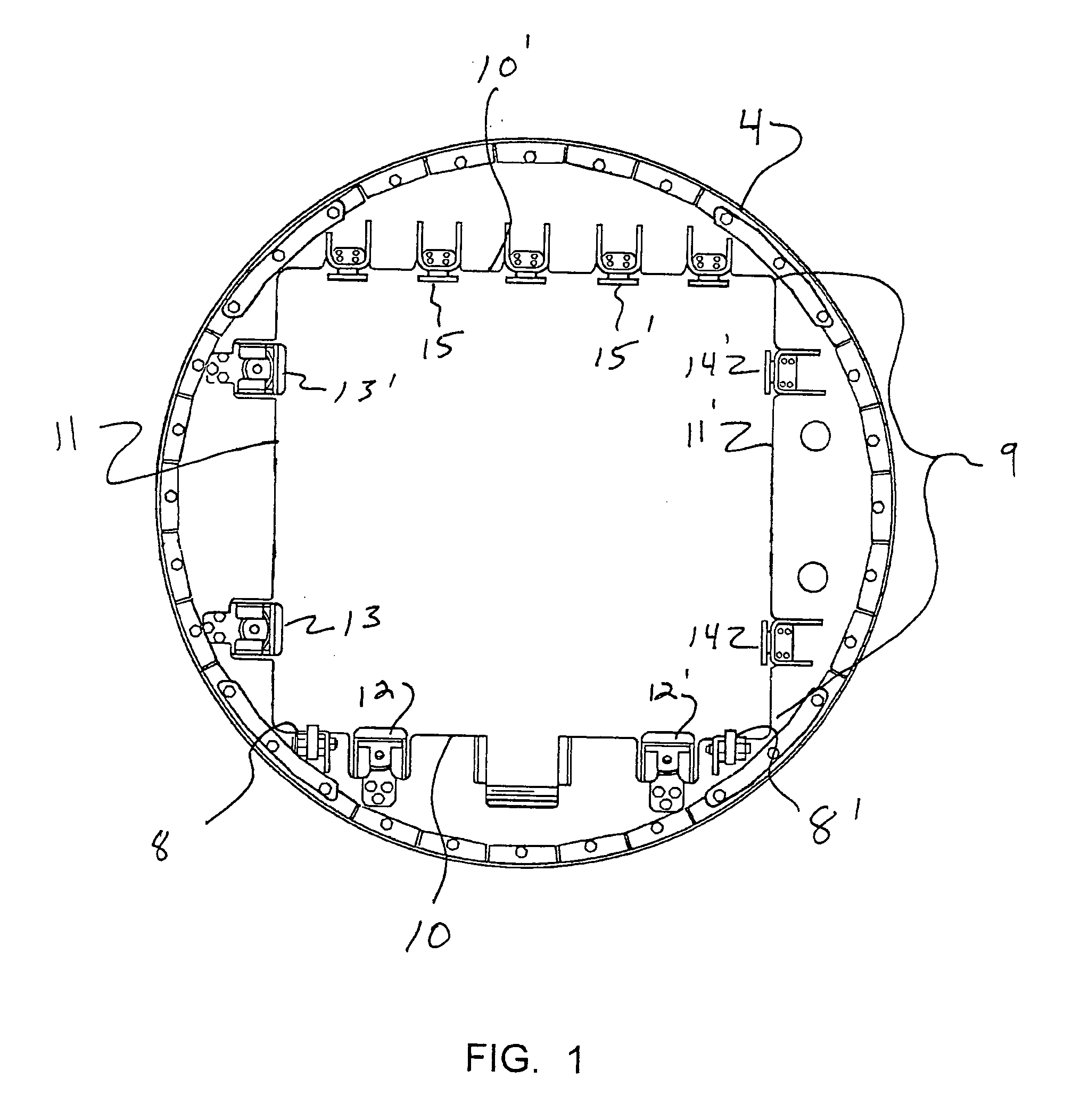
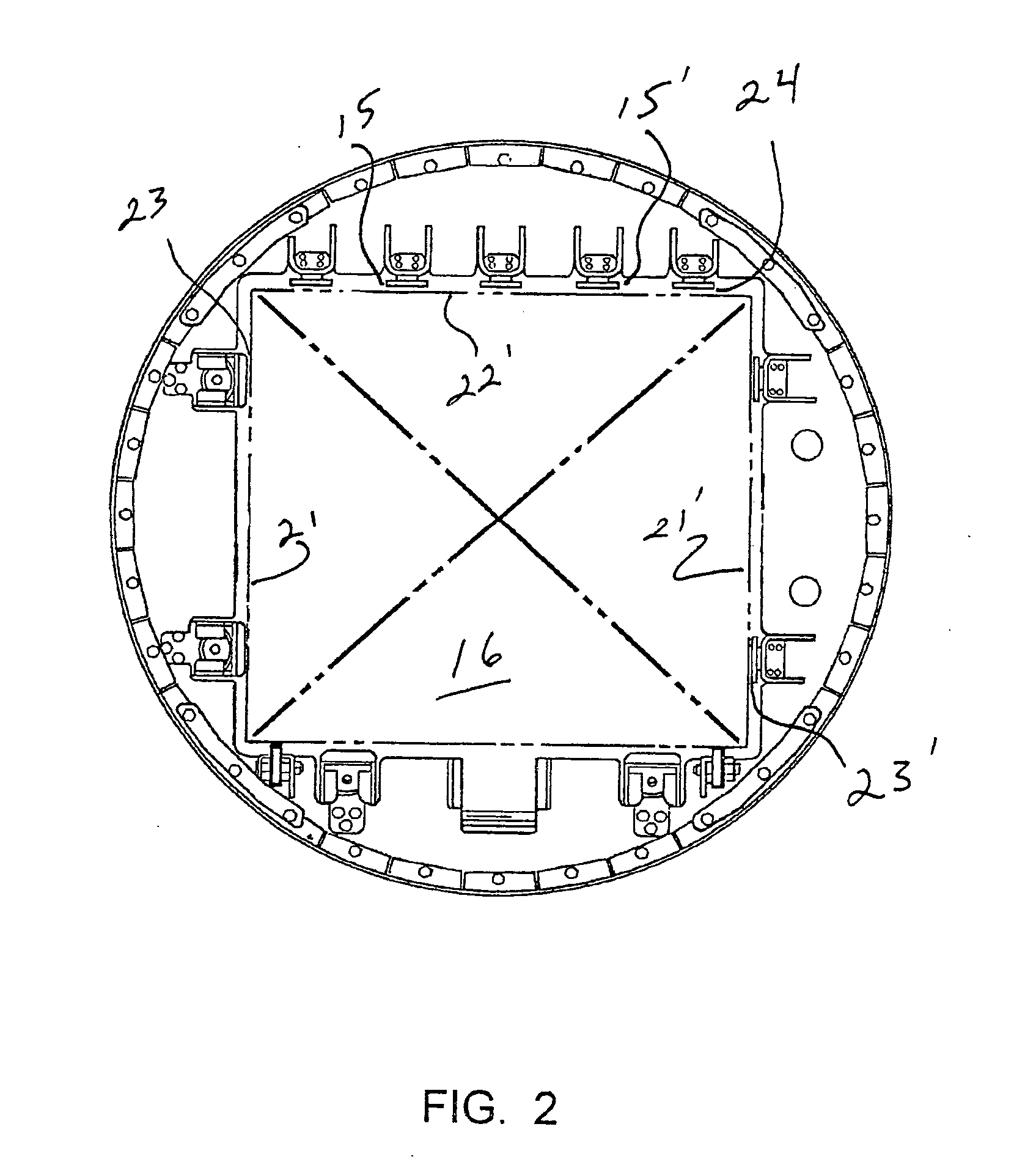
[0034] Referring to FIGS. 1, 2, 8 and 9 of the drawings, the system S of the exemplary embodiment of the present invention is shown implemented in conjunction with a water immersion retort 1 wherein there is provided an upper, pre-heat water storage vessel 2 and a lower process vessel 3, although it is noted that the basket positioning / clamping system of the present invention may be utilized with other types of retorts and product treatment devices.

[0035] In the exemplary embodiment of the Figures, the water immersion retort is also a rotational retort, having a rotational insert 4 situated within the cylindrical cavity formed within the process vessel 3, the rotational insert 4 rotated 5 by a drive mechanism 6 during processing. The rotational insert 4 may included support wheels 7 for engaging the inner cylindrical wall of the process vessel 3, for supporting the insert and a load for end over end rotation within the cylindrical inner wall of ...


PUM

PropertyMeasurementUnit
Lengthaaaaaaaaaa
Pressureaaaaaaaaaa
Areaaaaaaaaaaa

Abstract

A system for securing a basket containing product securely within an autoclave or retort. The preferred embodiment of the present invention is used with rotational retorts, which generally include a rotational insert for receiving product-loaded baskets, the rotational insert rotated via a drive to rotate the baskets end over end during the autoclave process, for more efficient heat transfer. The present invention contemplates an improvement for securing the baskets within the retort, to facilitate secure rotation of the baskets and their contents, and prevent shifting of the baskets within the retort during rotation. Particularly, the preferred embodiment of the present invention contemplates the use of one or more lift bladders sandwiched between clamping platens situated along the length of the rotational insert, the lift bladders configured to expand to lift and position the baskets into a securing position for rotation, then deflate to release the baskets after processing for removal.

Description

TECHNICAL FIELD OF THE INVENTION [0001] The present invention relates to clamping devices for use in sterilization autoclaves (known in the industry as retorts), and in particular to a system for securing a basket or series of baskets containing product securely within a retort. [0002] The preferred embodiment of the present invention is used with rotational retorts, which generally include a rotational insert for receiving product-loaded baskets, the rotational insert rotated via a drive to rotate the baskets end over end during the autoclave process, for more efficient heat transfer to the product. [0003] The present invention contemplates an improvement for securing the baskets within the retort, to facilitate secure rotation or other repositioning of the baskets and their contents, and prevent shifting of the baskets within the retort during rotation or repositioning. [0004] The improvement in the present invention lies in the utilization of a new and unique bladder system for s...

Claims


Application Information

Patent Timeline
IPC IPC(8): A23L3/00
CPCA23L3/001Y10T29/49938Y10T29/49877A23L3/003Y02P60/85
Inventor GREVE, CHRISTOPHER G.
Owner ALLPAX PRODS
Why Eureka
Try Eureka