Method and apparatus for controlling the pressure in a common rail system

a fuel injection system and pressure control technology, applied in the direction of electric control, fuel injecting pumps, machines/engines, etc., can solve the problems of unstable current control circuit, quality of rail pressure control may then suffer, etc., to improve emergency operation, increase the stability of current control circuit, and eliminate temperature dependence

Active Publication Date: 2006-06-22
ROLLS ROYCE SOLUTIONS GMBH
View PDF10 Cites 33 Cited by
  • Summary
  • Abstract
  • Description
  • Claims
  • Application Information

AI Technical Summary

Benefits of technology

[0008] The invention provides for a rail pressure control circuit with a subordinated current control circuit wherein the control value of the rail pressure controller is the guide value for the current control circuit and, at the same time, the input valve for a preliminary control. To provide an emergency running capability as an error protection, it is provided that, upon occurrence of non-logical actual current values, the current controller is de-activated and the PWM signal for controlling the suction throttle valve is determined exclusively by the preliminary control. In order to increase the stability of the current control circuit, filters are provided in the feedback branch.
[0009] The advantages of the invention reside in the elimination of the temperature dependency of the high pressure control, an improved emergency operation upon failure of the rail pressure controller for the same operating point and a secure emergency operation upon failure of the current measurement of the current control circuit.

Problems solved by technology

However, this may be problematic as the quality the rail pressure control may then suffer upon failure of the pressure sensor.
Since a current controller must be highly dynamic the application of an unfiltered PWM signal may result in an instability of the current control circuit.

Method used


Image

  • Method and apparatus for controlling the pressure in a common rail system
  • Method and apparatus for controlling the pressure in a common rail system
  • Method and apparatus for controlling the pressure in a common rail system

Examples


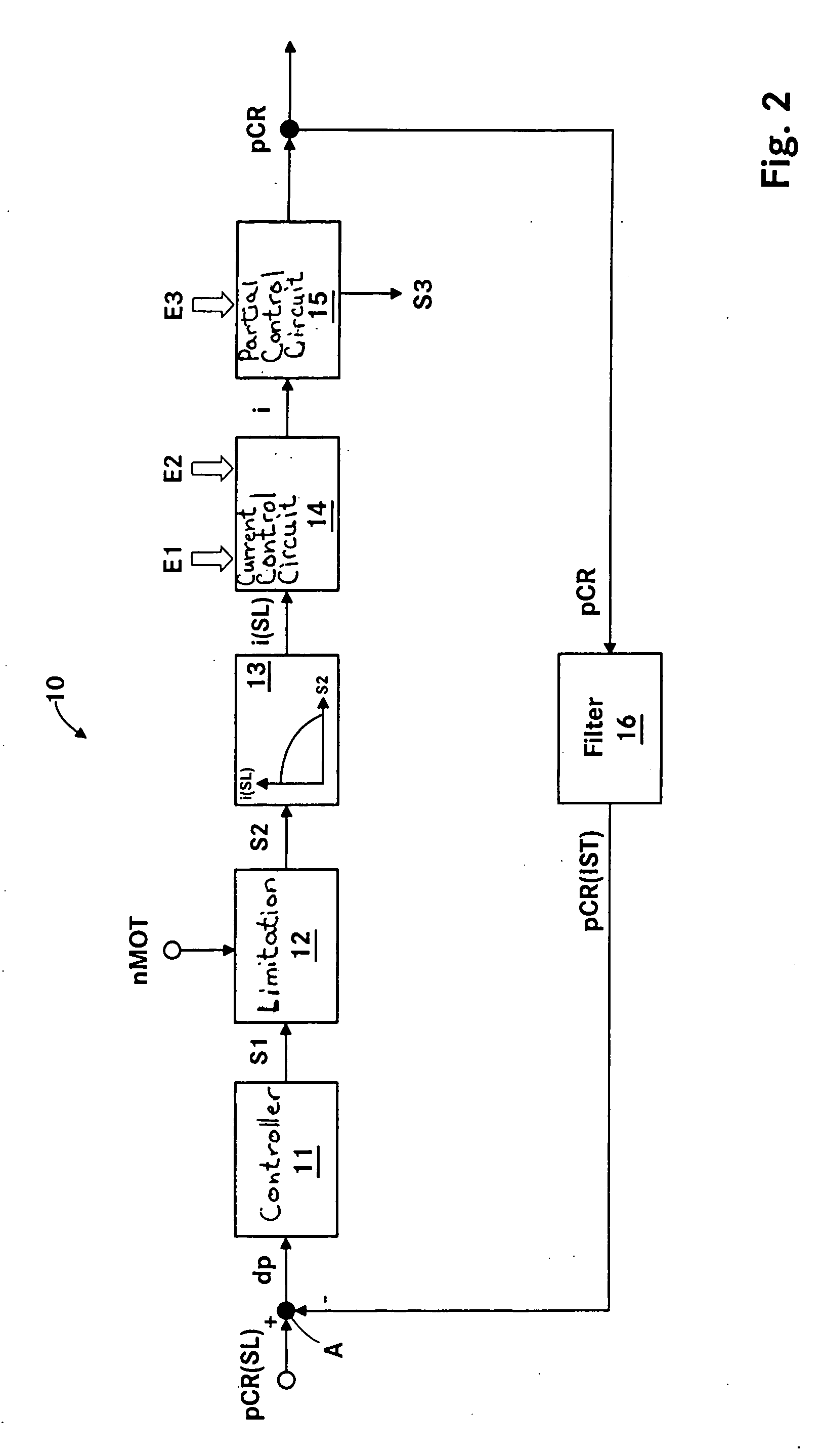
Embodiment Construction

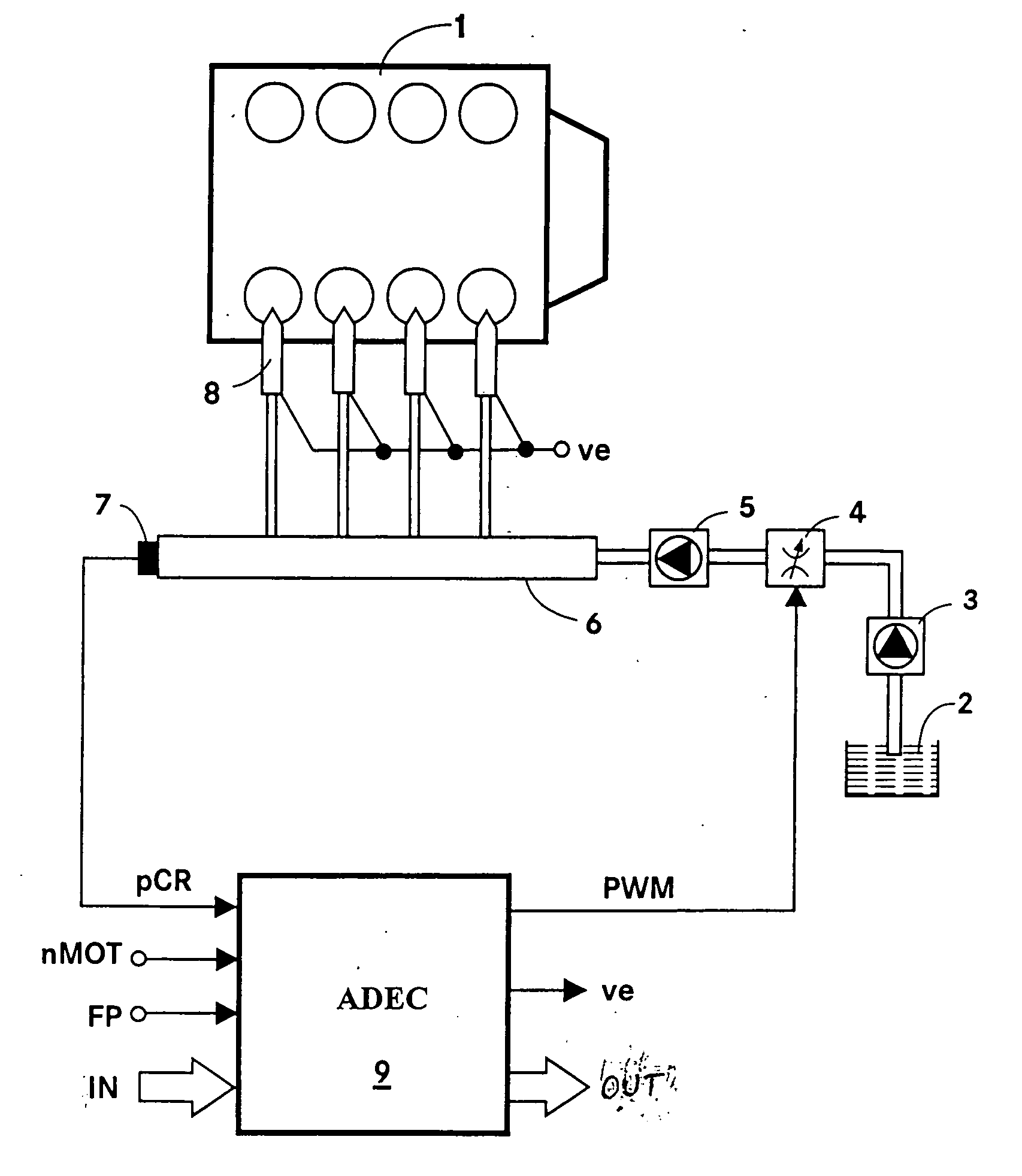
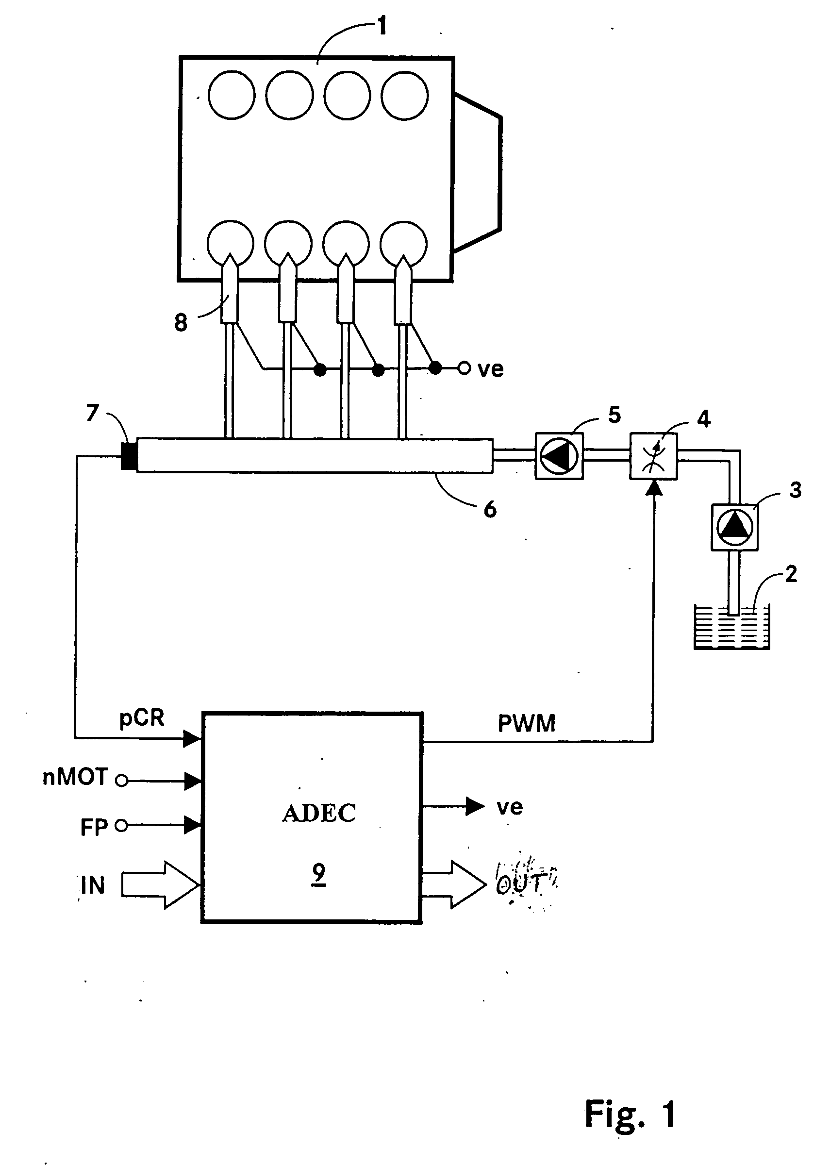
[0016]FIG. 1 shows diagrammatically a system overview of an internal combustion engine 1 including a common rail fuel supply system. The common rail fuel supply system comprises the following components: a low pressure pump 3 for pumping the fuel from a fuel tank 2, a variable suction throttle valve 4 for controlling the fuel volume flow through the valve 4, a high pressure pump 5 for increasing the fuel pressure, a rail 6 for storing the fuel under pressure and injectors 8 for injecting the fuel from the rail 6 into the combustion chambers of the internal combustion engine 1.

[0017] The operation of the internal combustion engine 1 is controlled by an electronic control apparatus (ADEC) 9. The electronic control apparatus 9 includes the usual components of a microcomputer system such as a microprocessor, I / O components, a buffer and storage components (EEPROM, RAM). In the storage components, the operating data relevant for the operation of the internal combustion engine or stored ...


PUM


Abstract

In a common rail operating method and system, an arrangement for controlling the rail pressure is provided with a rail pressure controller including a current control circuit for controlling a suction throttle valve operating current (i) which valve is arranged in the fuel supply line to a high pressure pump supplying high pressure fuel to the common rail. The suction valve operating current control circuit includes a preliminary control value generator which serves also as an emergency control signal generator for the control of the suction valve if an error occurs in the system at least to permit an orderly engine shutdown procedure.

Description

BACKGROUND OF THE INVENTION [0001] The invention relates to a method and an apparatus for controlling the fuel pressure in a common rail fuel injection system, wherein a rail pressure deviation is determined by a comparison of the desired and the actual rail pressure and wherein a rail pressure control value for controlling a throttle valve by way of a rail pressure controller is calculated from the rail pressure control deviation and the fuel supply to a high pressure pump and, consequently, the rail pressure is controlled. [0002] In a common rail fuel injection system, the fuel is pumped by a low-pressure pump from the fuel tank to a high-pressure pump. The high-pressure pump supplies the fuel with an increased pressure to a rail (high pressure storage). In the flow path between the low pressure pump and the high pressure pump, there is a controllable suction throttle valve by way of which the fuel admission to the high pressure pump is controlled. [0003] DE 103 30 466 B3 disclose...

Claims


Application Information

Patent Timeline
Patent Type & Authority Applications(United States)
IPC IPC(8): F02M59/36
CPCF02D41/221F02D41/3854F02D2041/1409F02D2041/1422F02D2041/2027F02D2041/2048F02D2041/224F02D2200/503F02D2250/31F02M55/007F02M63/0225
Inventor DOLKER, ARMIN
Owner ROLLS ROYCE SOLUTIONS GMBH
Why Eureka
Try Eureka