
Hydraulic system having an emergency release mechanism for a clutch having servo-assisted pedal actuation

Inactive Publication Date: 2006-06-22
SCHAEFFLER TECH AG & CO KG
View PDF4 Cites 13 Cited by
  • Summary
  • Abstract
  • Description
  • Claims
  • Application Information

AI Technical Summary

Benefits of technology

[0006] It is, therefore, an object of the present invention to enable the clutch to be disengaged in the event of a system failure, by using the clutch actuation and by employing a simple means.
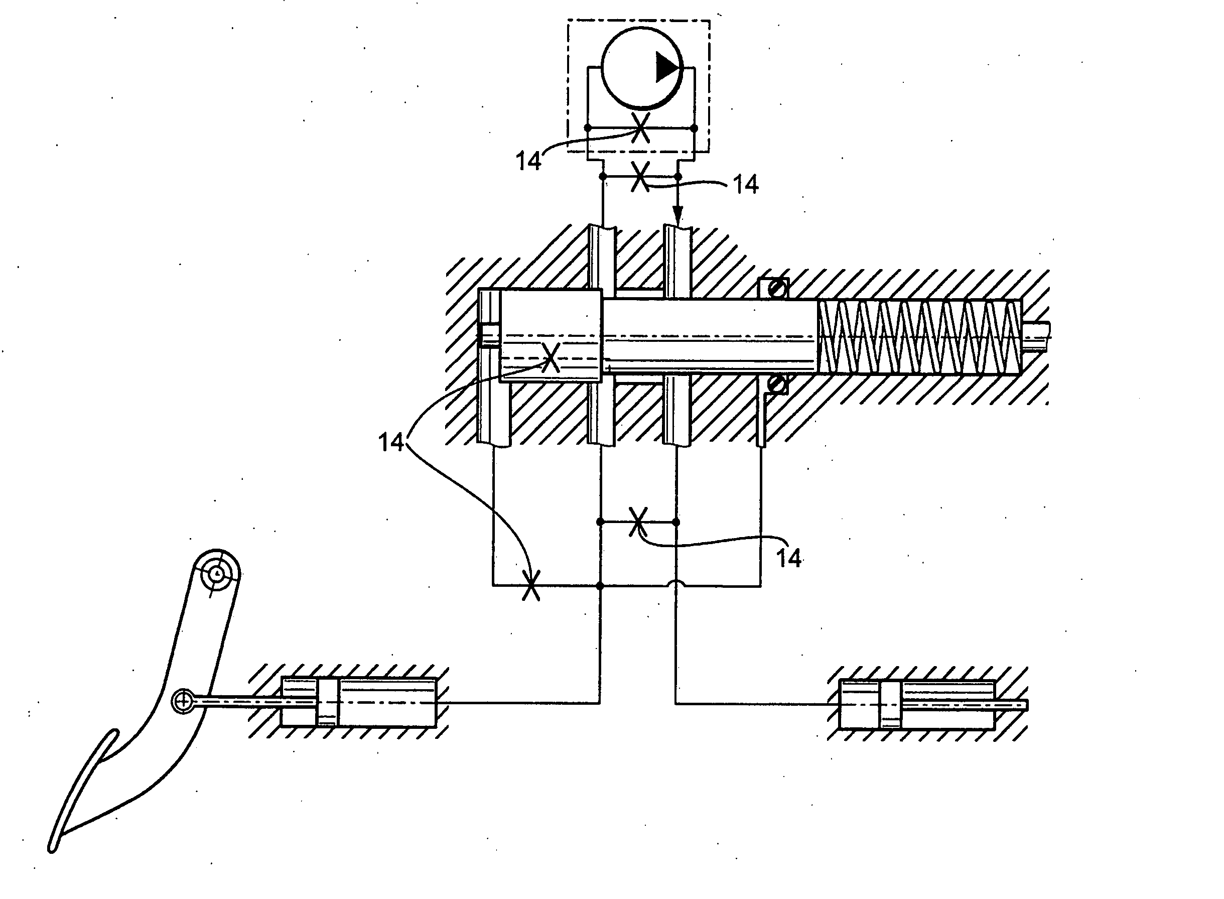
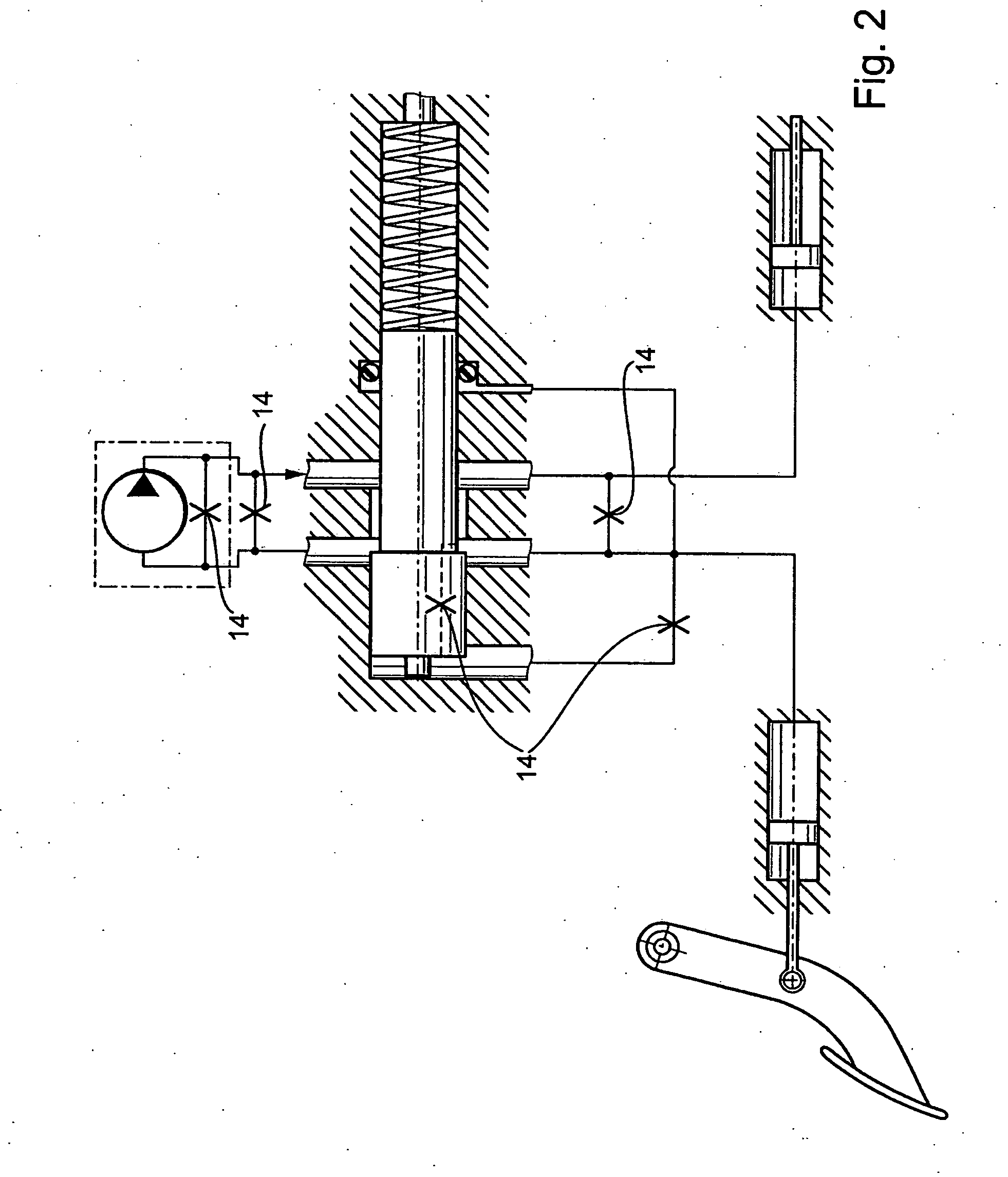
[0008] This emergency release mechanism may be advantageously constituted of at least one leakage site, which may be an orifice, nozzle or vent, or even a gap. The purpose of this at least one leakage site in the hydraulic system is to permit pressurized media to escape from the hydraulic system by actuating the clutch pedal with an increased expenditure of force, thereby reducing the pressure and, as a result, enabling the clutch to be disengaged. This method of reducing pressure in the hydraulic system in order to disengage a clutch in case of an emergency, represents an especially cost-effective variant.
[0011] In this embodiment, it may be especially beneficial for an overpressure function to be directly integrated into the valve block in this manner, since it eliminates the need for introducing additional components into the hydraulic system to effect a pressure reduction.

Problems solved by technology

Thus, a slight rise in pressure in the hydraulic system downstream of the master cylinder already causes a “failure in the system” to be signaled in the pressure relief valve, which immediately responds.

Method used


Image

  • Hydraulic system having an emergency release mechanism for a clutch having servo-assisted pedal actuation
  • Hydraulic system having an emergency release mechanism for a clutch having servo-assisted pedal actuation
  • Hydraulic system having an emergency release mechanism for a clutch having servo-assisted pedal actuation

Examples


Embodiment Construction

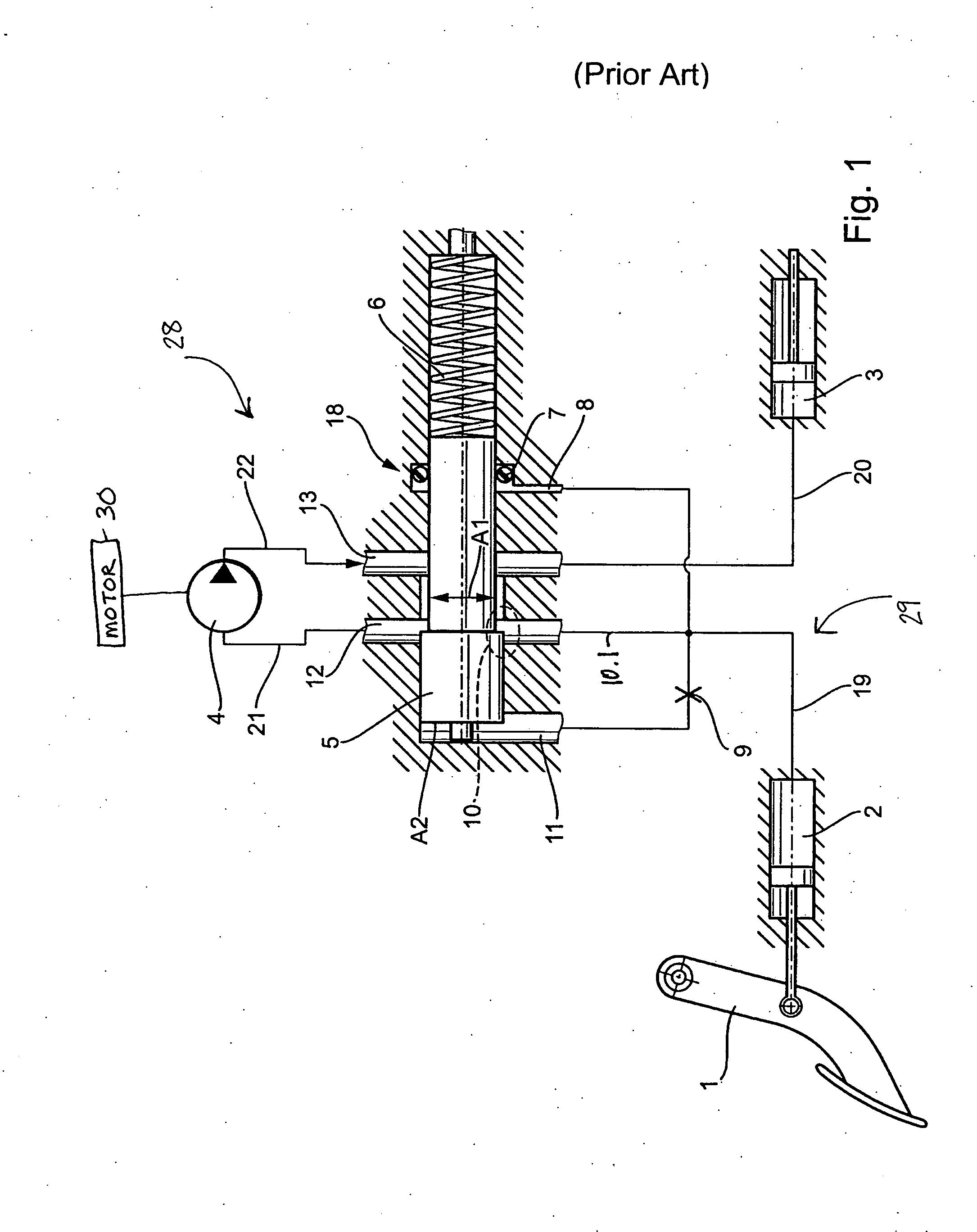
[0017]FIG. 1 schematically illustrates a related art an assistance for a pedal force actuation without the use of an emergency release mechanism according to the present invention. This servo power assistance is advantageously employed between a first line section 19 and a second line section 20, thus between master cylinder 2 and slave cylinder 3, and is constituted of a hydraulic pump 4 having an upstream valve block 18. Valve block 18 may just as well be located directly at master cylinder 2 or slave cylinder 3. Located essentially in the housing of valve block 18 are a pressure slide valve 5 and a pressure-valve spring 6, slide valve 5 being pressurized by pressure-valve spring 6 in response to its specific spring force. A seal 7 can be connected via a line 8 to the first line section 19. Valve block 18 has a plurality of connection ports, which communicate with pressure channels 11, 12 and 13. Pressure channel 13 is not only connected to valve block 18, but to second line secti...


PUM


Abstract

To disengage a clutch using the clutch actuation in the event of a failure of the system, having pedal force-assisted pressurization of the hydraulic system, composed of two hydraulic circuits, a master cylinder and a slave cylinder being essentially disposed in the first circuit, and an electromotor-driven pump being in the second circuit, and the two circuits communicating with one another in a mutually controllable fashion via a valve block having a pressure slide valve and a pressure-valve spring, an emergency release mechanism is provided in the hydraulic system.

Description

[0001] This claims the benefit of German Application No. 10 2004 062 981.1, filed Dec. 22, 2004 and hereby incorporated by reference herein. BACKGROUND [0002] The present invention is directed to a hydraulic system for pressurizing a clutch having an emergency release mechanism, into which a device for increasing pressure is integrated in order to reduce the pedal force. Typically, such a pressure increase is produced by an electrical pump, which additionally increases the pressure between the master cylinder and the slave cylinder in the hydraulic system. This pump is electronically controlled by pressure sensors, for example, since the pump pressure is dependent on the pressure prevailing in the hydraulic system. However, when this pump or the electromotor experiences a failure, the clutch is not able to be actuated, not even in response to an increased expenditure of force. The reason for this lies in the structural design requirements of servo power assistance in normal operatio...

Claims


Application Information

Patent Timeline
IPC IPC(8): F16D25/00
CPCF15B20/004F16D48/04F16D48/02F16D2048/0221F16D2048/023F16D2048/0245F16D2048/0254
Inventor GRETHEL, MARCOBENZ, FRANZ
Owner SCHAEFFLER TECH AG & CO KG
Learn More