Systems and methods for improving position resolution of charge-sharing position sensitive detectors

a detector and position technology, applied in the field of imaging, can solve problems such as reducing the spatial resolution of generated images, and achieve the effect of improving position resolution

Inactive Publication Date: 2006-06-22
GENERAL ELECTRIC CO
View PDF4 Cites 10 Cited by
  • Summary
  • Abstract
  • Description
  • Claims
  • Application Information

AI Technical Summary

Benefits of technology

[0007] In accordance with certain embodiments of the present technique, an imaging system configured to provide improved position resolution is disclosed. The imaging system includes detector acquisition circuitry that is configured to acquire a plurality of rise-times and a plurality of amplitudes from a detector assembly that includes an array of one or more detector elements. The imaging system also includes position determining circuitry that is configured to determine a plurality of respective impact positions on each of the detector elements. The plurality of impact positions is based on at least the plurality of rise-times and the plurality of the amplitudes acquired by the detector acquisition circuitry.

Problems solved by technology

Therefore, as will be appreciated, limitations or deficiencies in position determination at the photodetection step (i.e., the detection and localization of the optical photons) may ultimately reduce the spatial resolution of the generated image.

Method used


Image

  • Systems and methods for improving position resolution of charge-sharing position sensitive detectors
  • Systems and methods for improving position resolution of charge-sharing position sensitive detectors
  • Systems and methods for improving position resolution of charge-sharing position sensitive detectors

Examples


Embodiment Construction

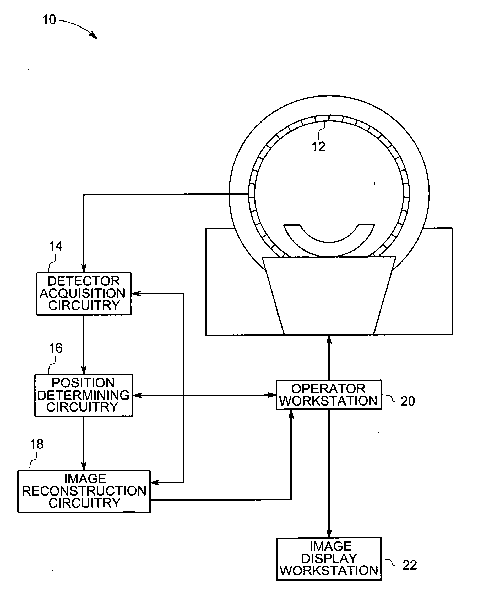
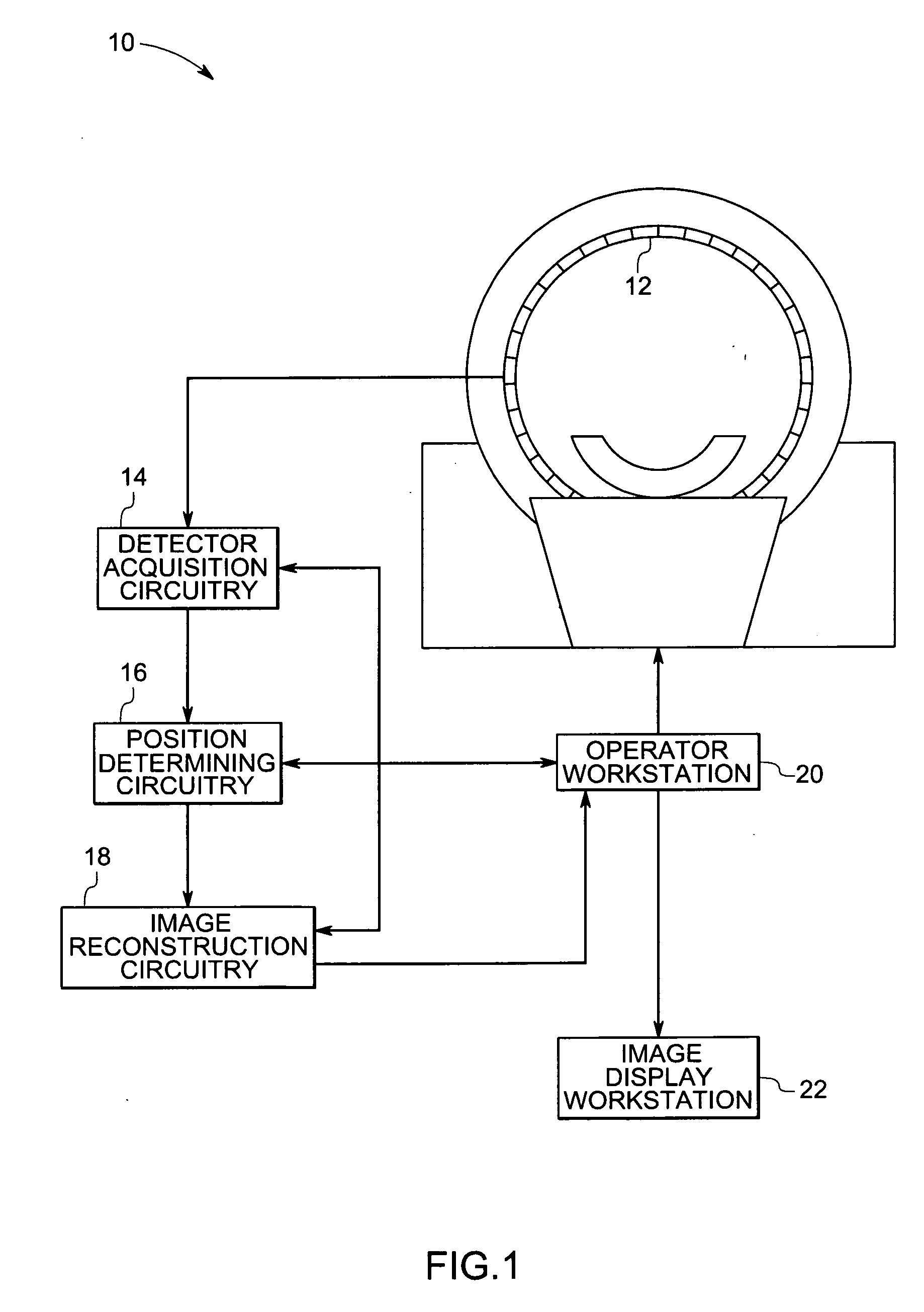
[0015] Turning now to the drawings and referring first to FIG. 1, an exemplary PET system 10 operating with certain aspects of the present technique is illustrated. The PET system 10 includes a detector assembly 12, detector acquisition circuitry 14, position determining circuitry 16, and image reconstruction circuitry 18. The detector assembly 12 typically includes a number of detector elements arranged in one or more rings, as depicted in FIG. 1. The PET system 10 also includes an operator workstation 20 and an image display workstation 22. While in the illustrated embodiment, the detector acquisition circuitry 14, the position determining circuitry 16 and the image reconstruction circuitry 18 are shown as being outside the detector assembly 12 and the operator workstation 20, in certain implementations, some or all of these circuitries may be provided as part of the detector assembly 12 and / or the operator workstation 20. Each of the aforementioned components would be discussed i...


PUM


Abstract

An imaging system configured to provide improved position resolution is disclosed. The imaging system includes detector acquisition circuitry that is configured to acquire a plurality of rise-times and a plurality of amplitudes from a detector assembly that includes an array of one or more detector elements. The imaging system also includes position determining circuitry that is configured to determine a plurality of respective impact positions on each of the detector elements. The plurality of impact positions is based on at least the plurality of rise-times and the plurality of the amplitudes acquired by the detector acquisition circuitry.

Description

BACKGROUND [0001] The invention relates generally to the field of imaging and more specifically to position sensitive detectors. [0002] The field of non-invasive imaging has broad and wide ranging applications in the areas of medical and industrial imaging. For example, in modern healthcare facilities, medical diagnostic and imaging systems are invaluable for diagnosing, and treating physical conditions and disorders inside the human body. In industrial applications, imaging is a valuable tool for scanning various objects for quality control and defect recognition. Commonly used imaging systems include computed tomography (CT) systems, x-ray systems, magnetic resonance imaging (MRI) systems, ultrasound systems, optical imaging systems, positron emission tomography (PET) systems, and single positron emission computed tomography (SPECT) systems. These various imaging systems can be used appropriately in both medical and industrial imaging applications. [0003] A primary advantage of no...

Claims


Application Information

Patent Timeline
Patent Type & Authority Applications(United States)
IPC IPC(8): G01T1/20
CPCG01T1/17G01T1/2985
Inventor BURR, KENT CHARLESIVAN, ADRIANLEBLANC, JAMES WALTER
Owner GENERAL ELECTRIC CO
Why Eureka
Try Eureka